
upload photo | donate | calendar
|
my profile |
register |
faq |
search upload photo | donate | calendar |
 09-16-2014, 02:50 AM
|
#1 |
|
User

Join Date: Oct 2007
Location: Maryland
Posts: 340
Thanks: 43
Thanked 107 Times in 51 Posts
|
All text and images that follow are copyright 2014 and are not to be used without the written permission of the author (me). In this thread, we'll be taking an in-depth look at a modern reproduction of the second model FG42 built in Decatur, Texas by Rick Smith and his team at Smith Manufacturing Group (SMG). The FG42 as originally built by the Germans in WWII has been well and extensively documented by a number of sources both in print and online with much of that material applicable to the SMG FG42 as well. Therefore, we will be touching on design characteristics and operation theory only in general terms and only when salient to the analysis. The main focus of this work is to provide detailed information about the rifle as built by SMG in an effort to assist you, the reader, in deciding whether or not this rifle is for you. Let's face it; this is an expensive rifle and I know that potential owners have many questions about it...I know I did. It's hard to drop $5000 on a firearm when the vast majority of information to be found encompasses nothing more than glamor shots and superficial descriptions. You need details and lots of them. Hopefully, I can provide at least some of those details.
I sat on the fence about this rifle for literally years. I really wanted one since sometime in 2010. That was when I first heard that they were being reverse engineered (that is an accurate description as SMG didn't even have an original rifle to work from). I was aware of SMG's reputation but, as a general rule, I almost never buy firearms that are not actually built by a military manufacturer. I've always found that they just don't hold up to heavy use. That thought was always in the back of my mind as I searched for information about this "new" FG42. But the more I looked, the more frustrated I became. There were always plenty of pretty pictures to be found but very little substance. Ian McCollum's range and disassembly videos, while excellent, still didn't answer all of my questions. Finally, I decided that the only way to get the answers I sought was to buy one for myself so I resolved to pick one up when the opportunity presented itself. That opportunity came in the form of a complete package including rifle (unfired other than by SMG), bayonet, sling, Meopta scope, Estes Adams scope mounting rings and 8 magazines. Well, I've gotten a lot of answers and I'll get more as time goes by. The answers I've gotten so far are the substance of this thread. I'm going to take this thing apart as far as is practical and post detailed pictures with descriptions as well as my thoughts about the SMG FG42. Later, I'll update this thread with range reports, tests in various adverse conditions and continuing thoughts as time goes by. If I do my job correctly, you will be provided with enough information to determine whether or not this is the right purchase for you. As always, please feel free to contact me if I've missed anything or do not answer a question you may have. I will be happy to help if I can. Prior to writing this, I contacted Rick Smith for some statistical information and to notify him of my intentions. He was very helpful in his answers and heartily encouraged me in my work. To quote Mr. Smith: "It can cause some anxiety for the maker of that weapon but that's just the way it is! It works and is good or here are its failings." As always, this is going to be a multi-post essay created over a number of days simply because there is so much material to cover. Please bear with me and check back now and then. Okiedokie, I think that covers all the preliminaries so let's get to work!
__________________
I promise to be nice and play well with others |

|

|
| The following 3 members says Thank You to Wilhelm for your post: |
|
09-16-2014, 02:51 AM
|
#2 |
|
User
Join Date: Oct 2007
Location: Maryland
Posts: 340
Thanks: 43
Thanked 107 Times in 51 Posts
|
Here we have the 7.92x57 (8mm Mauser) semi automatic only FG42 as built by SMG:
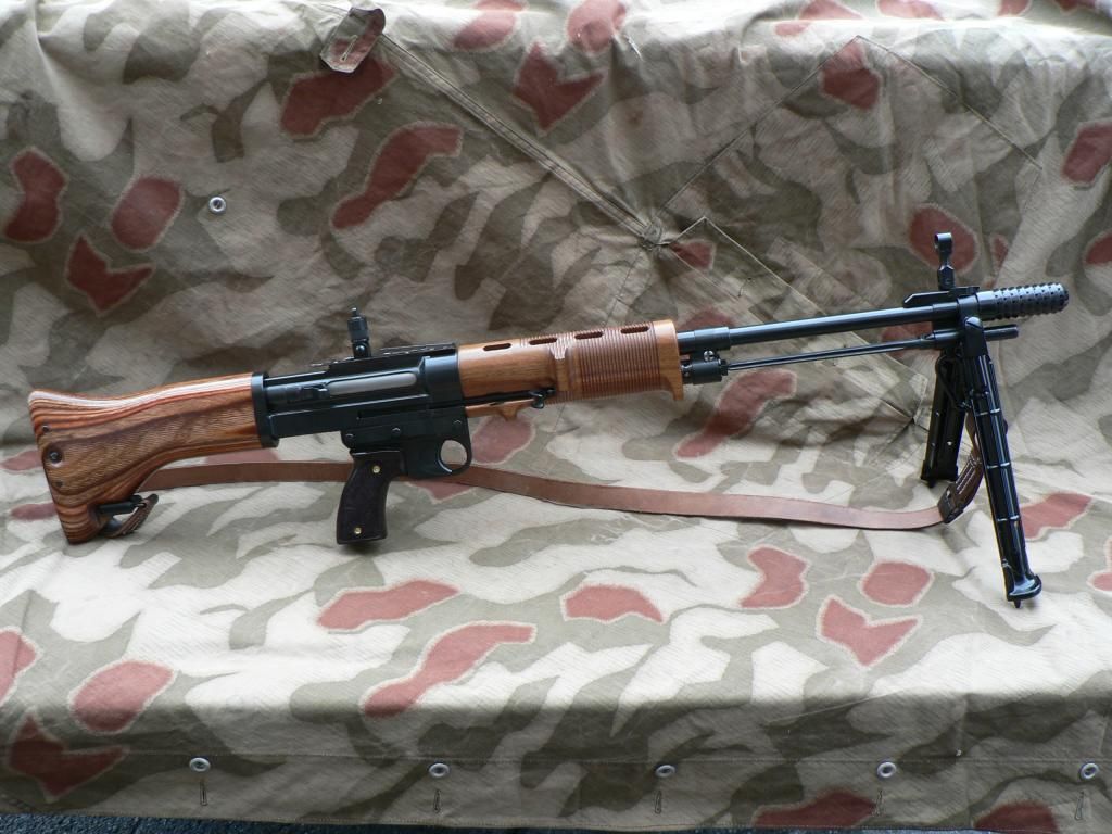 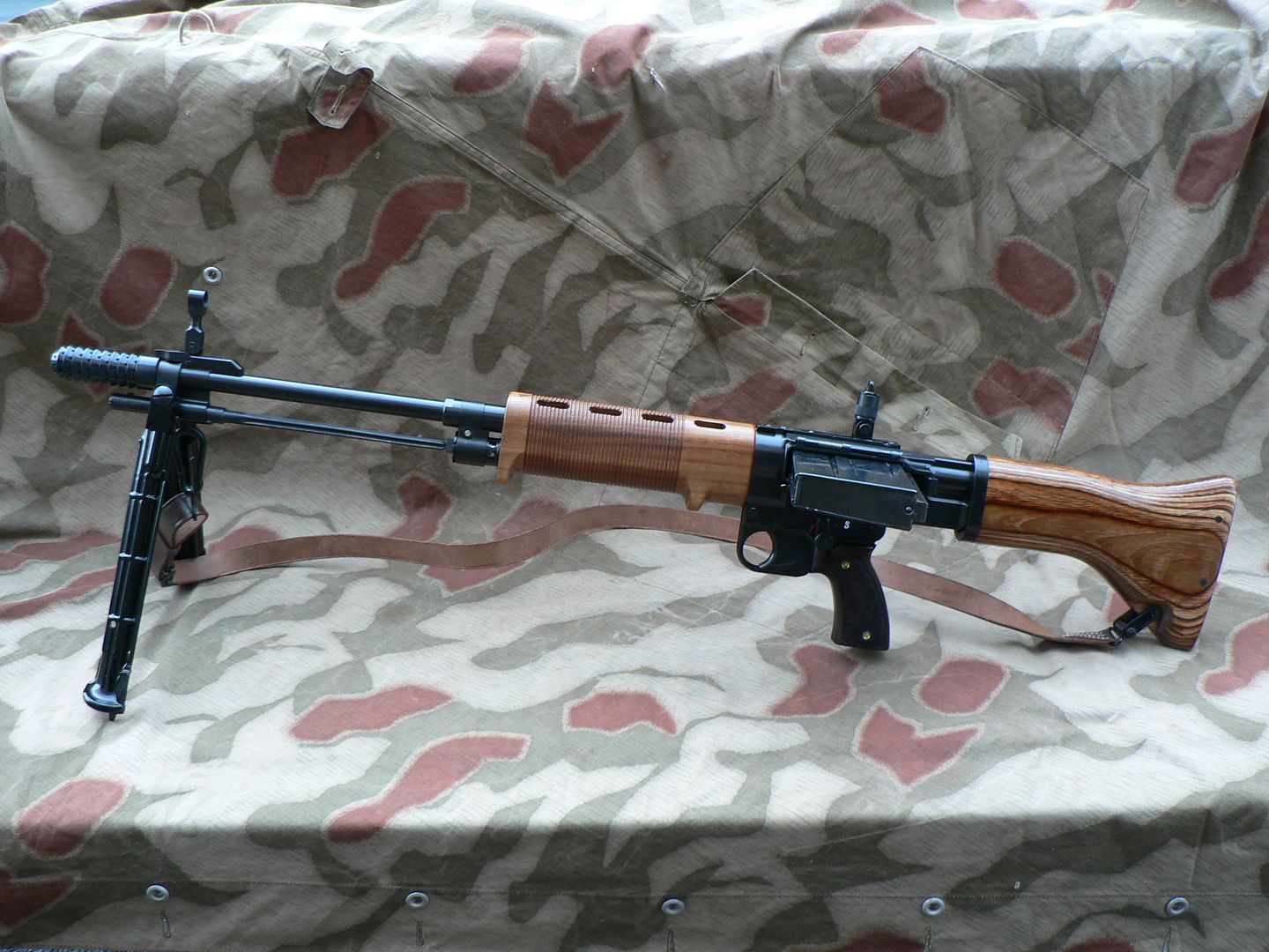 According to the manufacturer: Barrel length: 19.69" Overall length: 38.4" Weight with loaded magazine: 12.9 lbs. While it looks and operates very much like an original FG42, there are many differences. Some of those differences are out of necessity. For example, the original rifle made extensive use of stampings wherever possible including the receiver. SMG does not have the manufacturing capability to produce stamped parts. Therefore, other than the springs, a few rivets, the handgrips and bipod legs, EVERY SINGLE PART of this rifle is machined from solid stock. The receiver alone started as a roughly 13 pound block of steel and was machined down to around 2 pounds in its completed state. Nothing was an "off the shelf" part. All of it was specially built for this rifle. Because original FG42's are so rare SMG did not have a working rifle to take measurements from, relying instead on Shoei non firing replicas as well as lots and lots of research. It is also important to note that SMG did not have access to original spec sheets so metallurgical requirements had to be worked out through experience as well as trial and error. While they had a working prototype within three months of deciding to go ahead with the project, it took almost another year to get everything running to their satisfaction before finally shipping out the first rifles to customers in January of 2012. That leads us into differences from the original rifle intended to improve the design. Some of these changes include a stainless steel gas piston and gas regulator to combat the use of corrosive ammunition and a chrome lined barrel for the same reason. The above changes are only a few of the MANY changes implemented. Some of them I am completely unaware of. Others I know about and they will be discussed as we go along. I say all of this in an effort to make it crystal clear that, although close, this rifle is by no stretch of the imagination an exact copy of the WWII FG42. But, although I have never held or shot an original, I have researched them quite a bit and I am confident in saying that, from a material and build quality standpoint, this rifle is almost definitely superior to one. Time for some close-ups. We'll start at the front and work our way back.
__________________
I promise to be nice and play well with others |
|
|
|
| The following member says Thank You to Wilhelm for your post: |
|
09-16-2014, 02:51 AM
|
#3 |
|
User
Join Date: Oct 2007
Location: Maryland
Posts: 340
Thanks: 43
Thanked 107 Times in 51 Posts
|
First up is my favorite part of the FG42, the muzzle brake:
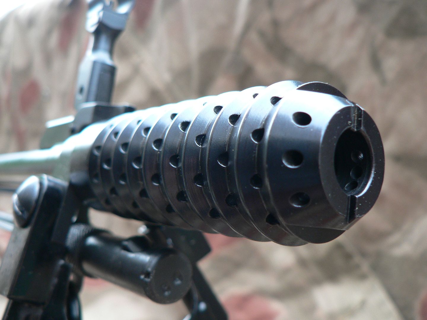 It is certainly NOT a flash hider because this thing make rather large balls of fire due to (I think) the short distance between the gas tap in the barrel and the end of the muzzle. There are 92 little holes drilled in this contraption in an effort to combat recoil. Sticking out forward from the base of the front sight is a sprung muzzle brake retaining latch that looks a little bit like a wishbone: 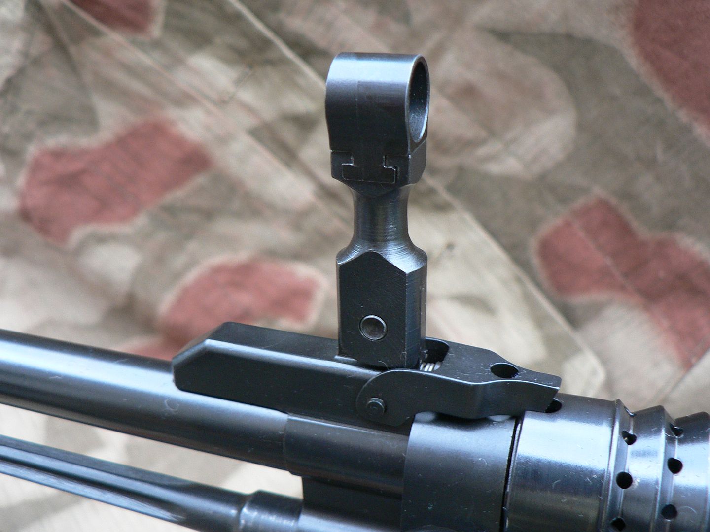 Notice how it fits into a notch cut into the rear of the brake. This holds the muzzle brake in place. To remove the brake, lift up on the front the wishbone retaining latch and turn the brake counter clockwise until it falls off the threads and into your hand. Here's a view down inside: 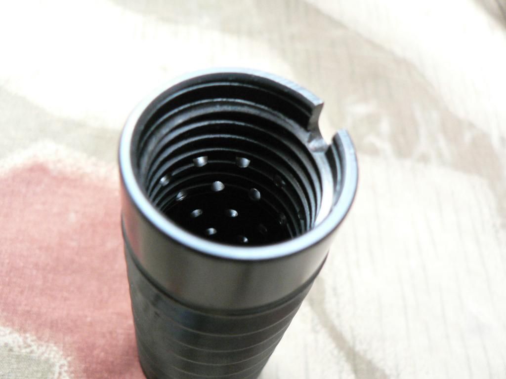 It's threaded partway down and then just smooth steel after that. The hole is plenty big enough to get your finger down inside for cleaning. If you're shooting corrosive ammo, just wash it out with water but make sure you dry it well before installation so as not to rust the threads. About reassembly....don't crank the muzzle brake down tight. Just snug it up until it stops and then back it off until the retaining latch engages the slot. The muzzle brake will wiggle on the threads just a little when properly locked on but this is normal. Here's the muzzle with the brake removed: 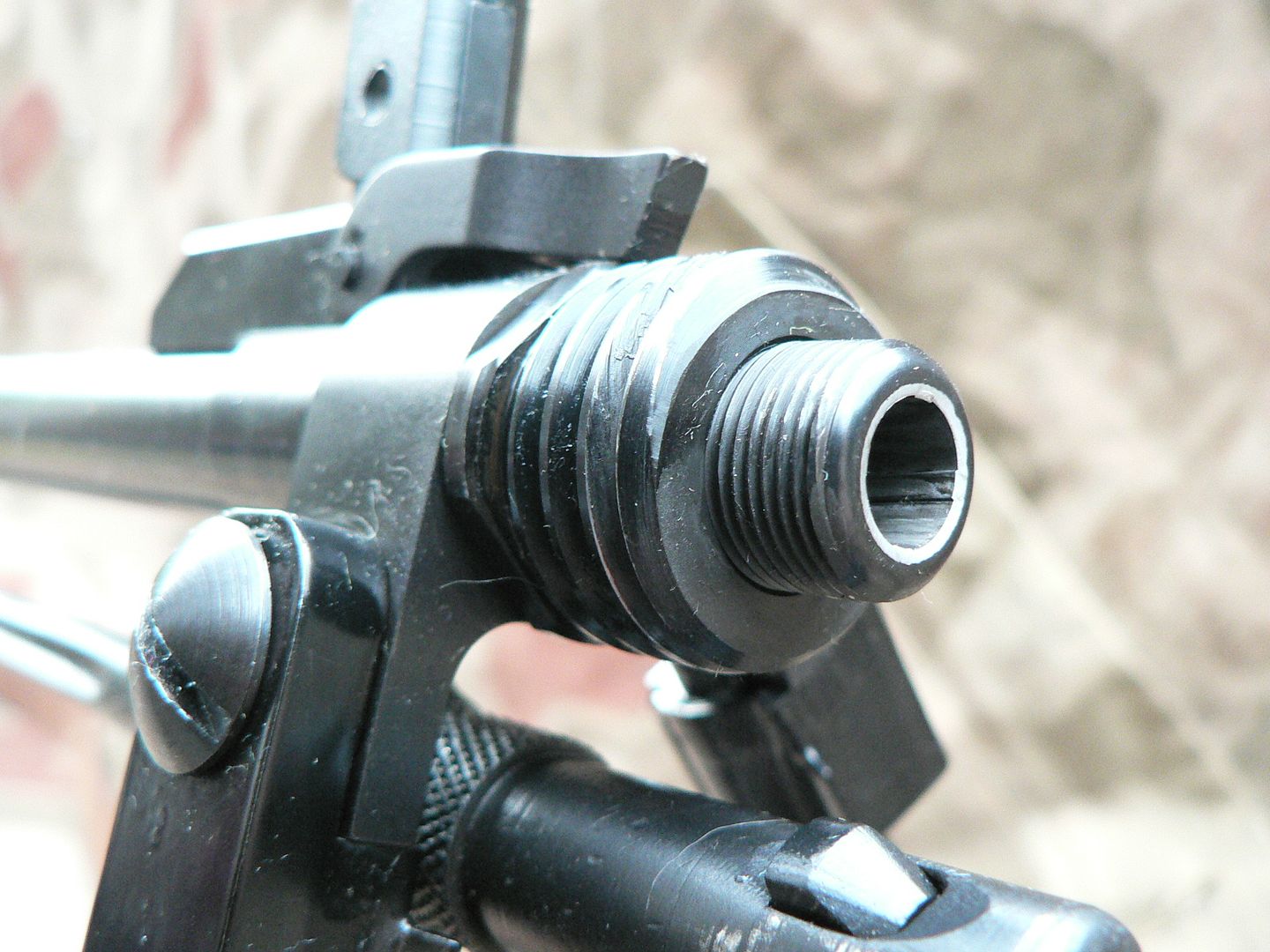 Hey! That barrel crown looks to be chromed! It is. Approximately the first 30 rifles had original MG42 barrels recontoured for this rifle. After that, production stopped for a bit while SMG looked for a manufacturer that suited them. They eventually selected Green Mountain as that manufacturer. The barrels are button rifled and chromed lined. While I am thrilled about the chrome lining since I am a huge fan of Combloc firearms which almost universally use chromed bores, I am far less enthusiastic about a button rifled barrel. IMO, hammer forging it THE way to go but I also know that is cost prohibitive to all but the largest of manufacturers. As much as I hate it, I just have to swallow my pride on that. I'm sure it'll outlast me as I don't plan on shooting 5 billion rounds out of this thing. Notice the large threads for the muzzle brake. This is an adapter screwed onto the barrel and held in place with locktite. Apparently, original adapters were peened in place but SMG felt more comfortable using locktite. Later, we'll look at the gas block retaining nut. It too uses locktite instead of being peened in place. SMG found that these two parts WILL disassemble themselves in use unless they are suitably locked. The muzzle brake adapter also holds the bipod and front sight assemble in place on the barrel. Hanging below the adapter is the bayonet. We'll look at that later. The big screw is holding the right bipod leg to the bipod mounting yoke. We'll look at that later too. Next up it the front sight: The little line seen running up the side of the sight hood is a machining mark, NOT a cast line. Remember, everything is machined; nothing is cast EXCEPT for the bipod legs which we will discuss a little later. At the base of the front sight is the muzzle brake retaining latch. If you look closely, you can see its spring and the pin that holds the latch to the sight base. Sticking out the back of the sight base is a square bar. This engages a flat area machined out of the barrel and keeps the sight from spinning on the barrel. Rising from the sight base is the six piece front sight assembly. At present, we can only see three of the six parts. Starting from the top, they are the sight hood, sight body and sight pivot pin. The unseen parts are the sight post, detent spring and detent plunger. Notice that the sight hood is dovetailed onto the sight body. On the original rifle, this was how you adjusted windage. You can do it that way on this rifle as well but it is NOT recommended because you run the risk of breaking the rather thin sight body. Rather, the rear sight has been modified from the original design to allow for windage adjustment. We'll look at that later too. (that's an awful lot of "later's" in there but I promise that we will get to it all.) Just in case you plan to be jumping out of airplanes with this rifle, it folds down so as not to get caught on your gear during the jump: 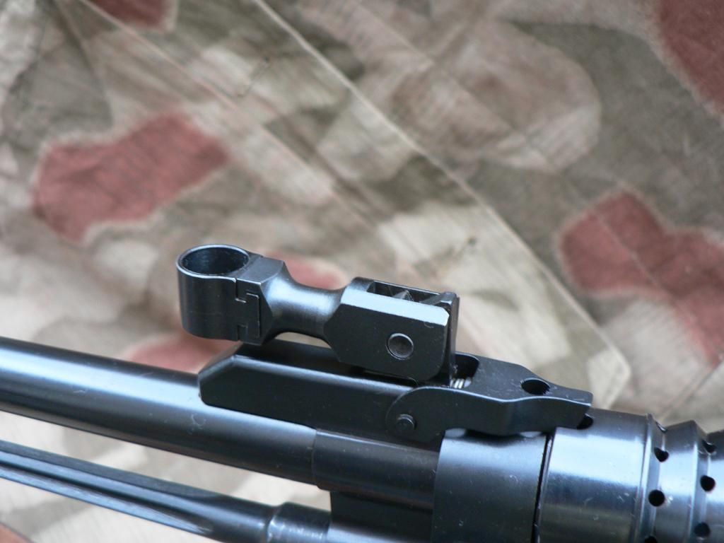 Simply pull back on the sight and it folds down with the detent plunger and spring locking it in place. To unfold it, simply grab the sight hood and pull up. It then locks in the up position. To adjust elevation, the front sight must be removed from the rifle. To do this, fold the front sight back slowly until it is resting at a 45 degree angle relative to the barrel: 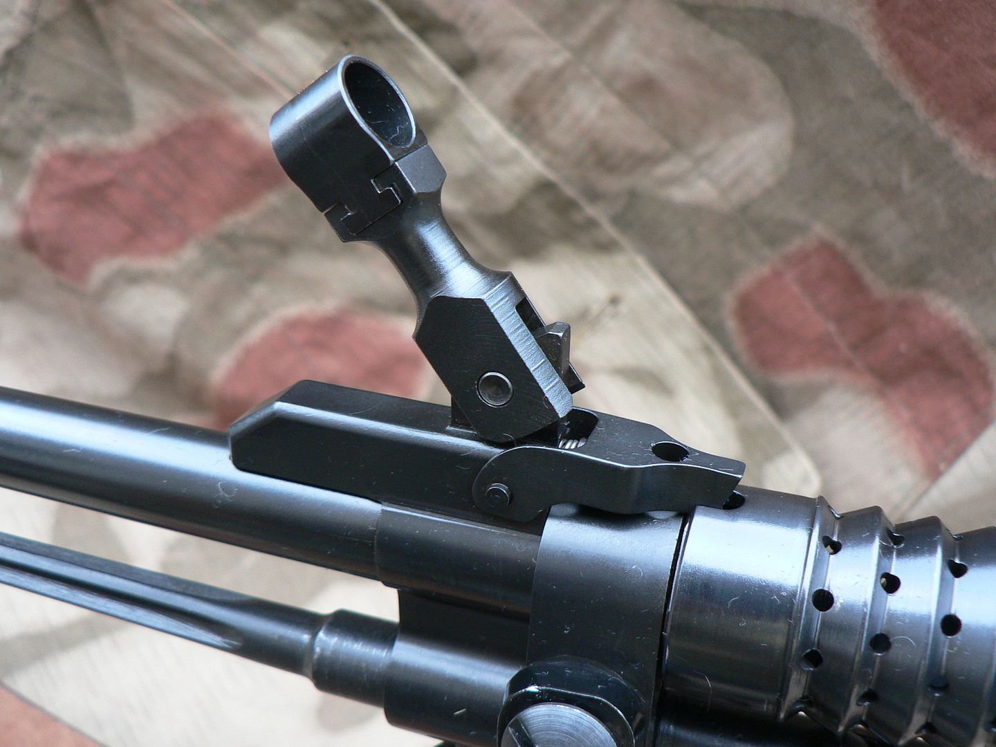 Then push straight down (relative to the sight body) on the sight hood with the palm of your hand. You will feel the detent spring inside the sight compress. While holding it in this position, use the tip of a bullet or similar object and push the pivot pin all the way out to either side. Then release pressure off the sight hood and remove the assembly from the sight base. Here's the sight base with the sight assembly removed: 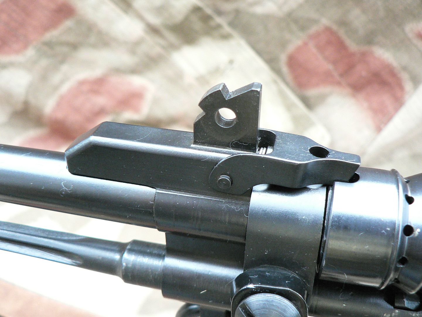 You can see the two notches that the detent plunger locks into to hold the sight in either the up or down position. Here's the front sight assembly removed from the rifle: 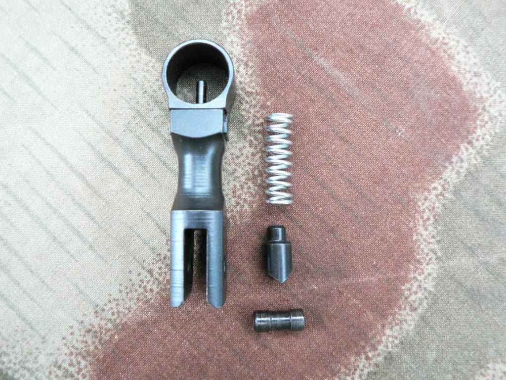 To adjust the elevation, a 1/16 hex wrench is inserted up through the sight body until it engages the bottom of the sight post. The front sight can then be screwed up or down. On the face of it, this way of adjustment seems like a big pain in the arse and it can be I'm sure. However, my rifle came perfectly zeroed for elevation at 100 yards so I had to do nothing. I can only assume that SMG zeros them before shipping them out... or maybe I just got lucky (unlikely). Here is a shot showing the right side of the sight assembly: 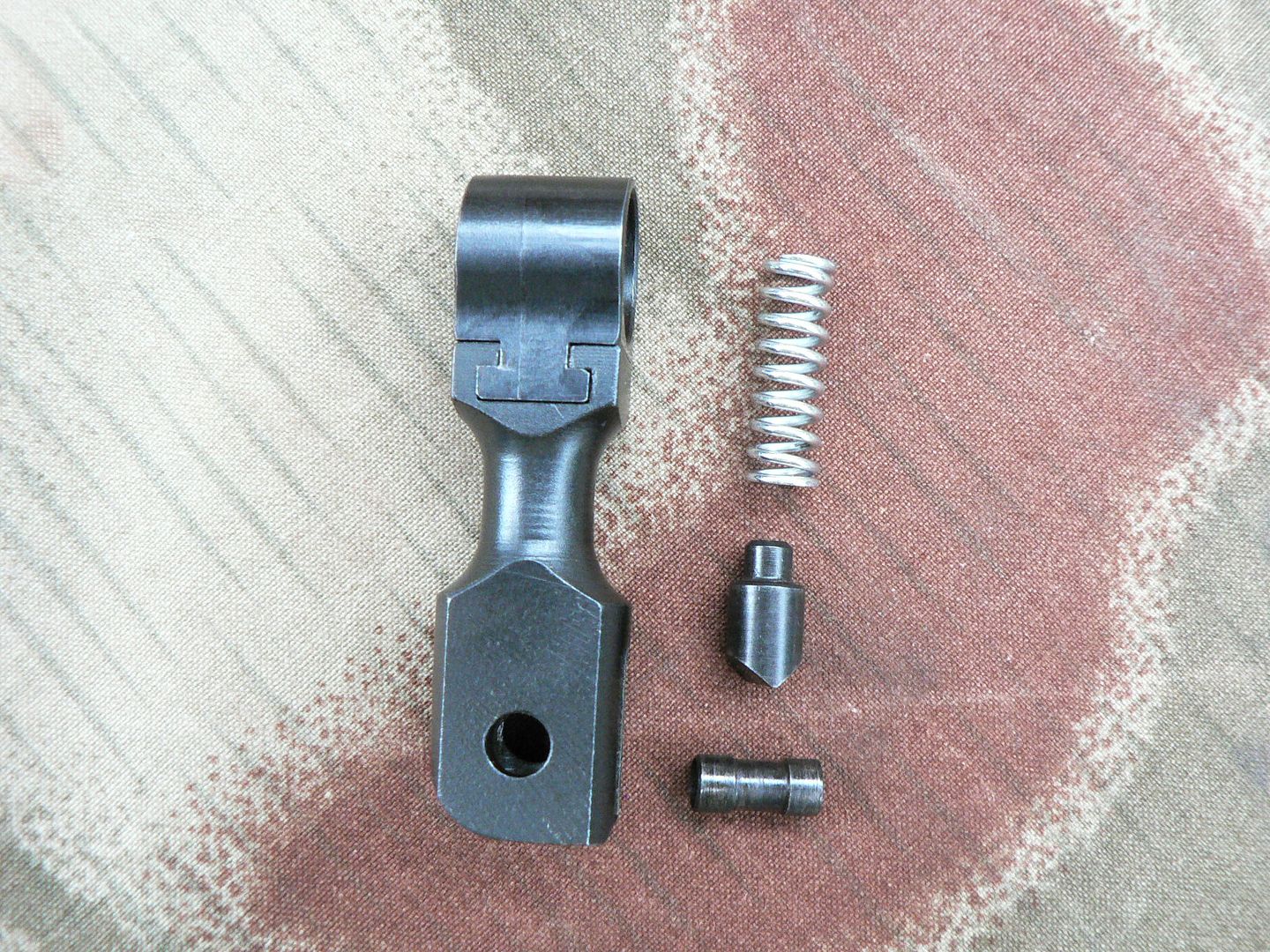 Notice that the lower rear of the sight body (lower left in the picture) is radiused while the lower front (lower right in the picture) is square. This radiused side MUST face to the rear upon reassembly or your sight will not fold. To the right of the sight assembly in the picture is the detent spring, detent plunger and pivot pin. The plunger has a "v" shape to it at the bottom. The way it is pictured is the way it must face when reassembled. Notice that the pivot pin is thinner in the center. This keeps it locked in place when assembled guaranteeing that it will not work its way out in use. The only way it can be removed is when the sight assembly is in the 45 degree position relative to the barrel and pressure downward pressure is applied to the sight hood. Assembly of the sight to the sight base is the reverse of removal. It all sounds very fidgety but it is actually very easy and natural in practice. The only thing that can get a little frustrating is keeping the holes lined up between the sight base and sight assembly while trying to insert the pivot pin. One you do it a time or two though, you get the hang of it. Well, that's it for tonight. I've been at this for hours and I'm getting tired. Time to hit the hay! Yeehaaa!!!
__________________
I promise to be nice and play well with others |
|
|
|
| The following member says Thank You to Wilhelm for your post: |
|
09-16-2014, 11:52 AM
|
#4 |
|
Moderator
2010 LugerForum Patron 
Join Date: Jun 2002
Location: Santa Teresa New Mexico just outside of the West Texas town of El Paso
Posts: 7,005
Thanks: 1,087
Thanked 5,139 Times in 1,689 Posts
|
That is a super impressive machine, but I doubt you can get it for $39.95 and 4 Nabisco Shredded Wheat box tops. Takes a lot of work and skill to crank out something like this.
__________________
If it's made after 1918...it's a reproduction |

|
|
|
09-17-2014, 01:36 AM
|
#5 |
|
User
Join Date: Oct 2007
Location: Maryland
Posts: 340
Thanks: 43
Thanked 107 Times in 51 Posts
|
Yes it does Ron. I think that many don't realize just how much work. The pictures clearly show just how much Quality is poured into the workmanship.
Picking up where we left off, let's take a look at the spike bayonet: 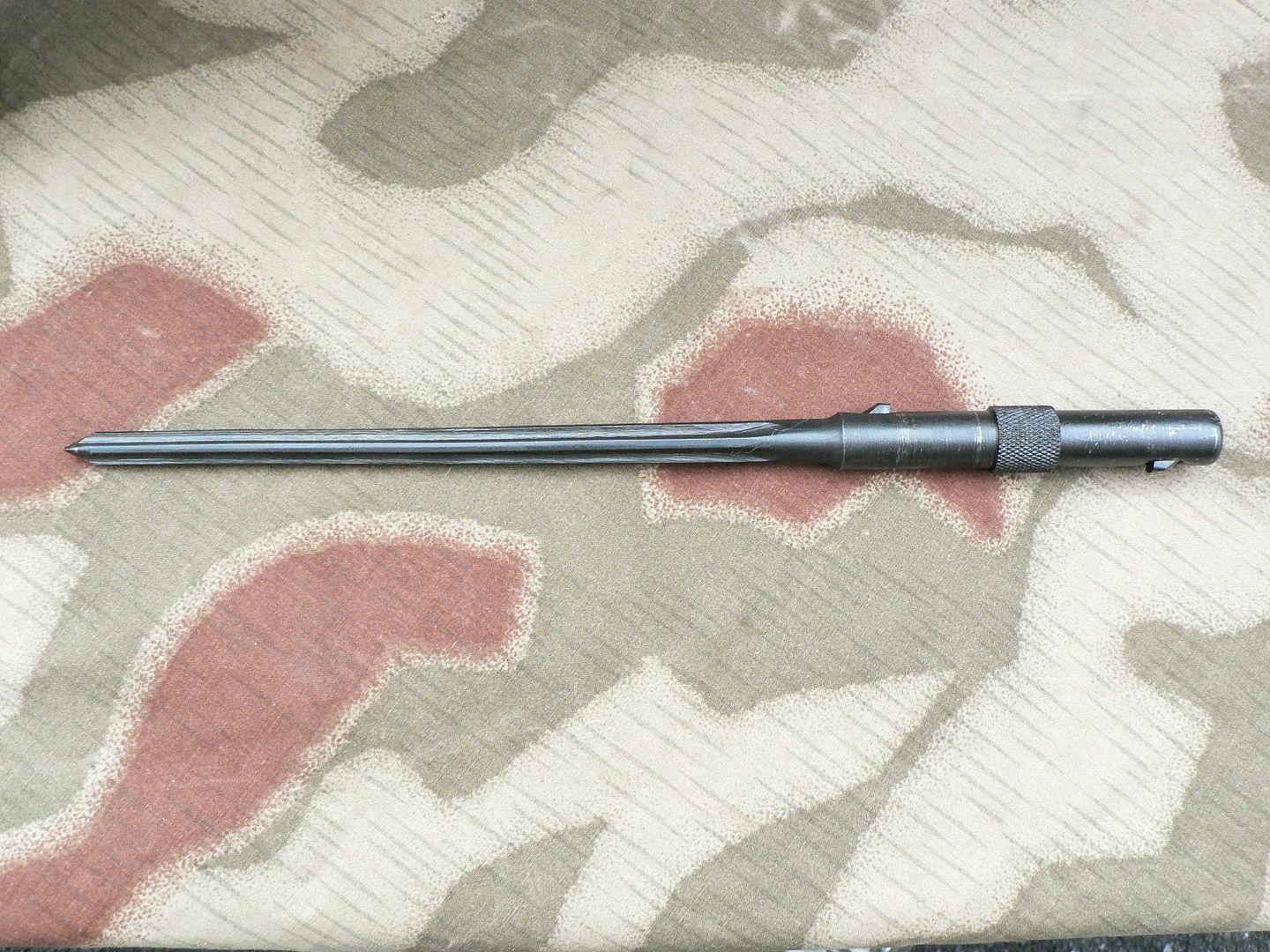 This part was not made by SMG for some reason nor is it supplied with the rifle. It started life as a much longer French made MAS 36 bayonet and was cut down to the proper length and blued to match the rifle by SMG. If you want one, YOU have to find one of these old and relatively obscure bayonets and YOU have to buy it and send it into them for modification. This rifle is a pretty complex piece of machinery and SMG figured out how to make every single part yet they don't make the bayonet. I must say that I don't quite understand the reasoning behind that one but that's just the way it is. The original German bayonet was copied from the MAS 36 too. Anyways, notice that there is a nub sticking up off the shaft both in front of and behind the knurled part of the shaft. These nubs are actually the ends of a spring loaded rocking bar concealed within the bayonet and are sticking out of holes cut in the shaft of the bayonet. They serve as the locking lugs that hold the assembly locked in either the deployed or the stowed position. Push down on one nub and the bar inside rotates pulling the other nub inside. The mounting tube that the bayonet fits into is part of the front sight base and is shown here hanging underneath the barrel: 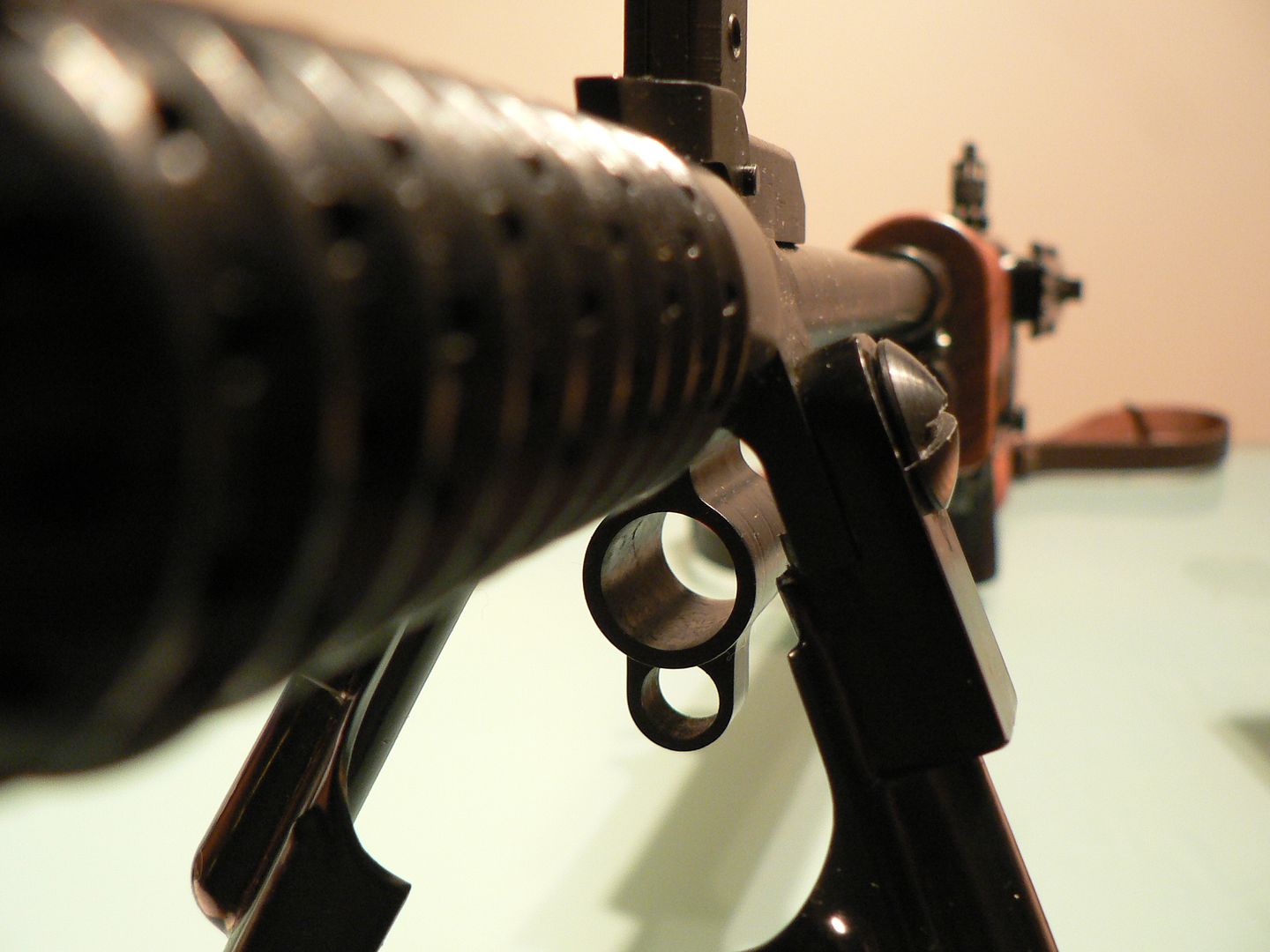 Below the mounting tube is a smaller ring that serves as the attachment ring for the sling carabiner (we'll look at the sling later). To mount/deploy the bayonet, you simply insert the rear of it into the mounting tube and push until it clicks into place. The knurled part of the shaft will stop the bayonet from being pushed further rearward and the rear locking nub will keep it from being pulled forward. Here's what it looks like deployed: 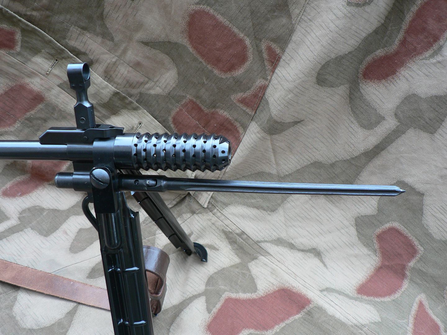 It doesn't look very substantial but I guess it's better than nothing. Once locked in place, the bayonet will freely rotate in the mounting tube. To remove the bayonet, press the forward locking nub into the shaft and pull the bayonet forward and off the rifle. To stow the bayonet, simply insert it into the mounting tube tip first and slide it rearward until it locks. Again, the knurled ring will stop its rearward movement and the front locking nub will hold it from sliding forward. As you are stowing the bayonet, notice that the tip engages a hollowed out area in the gas plug shown here: 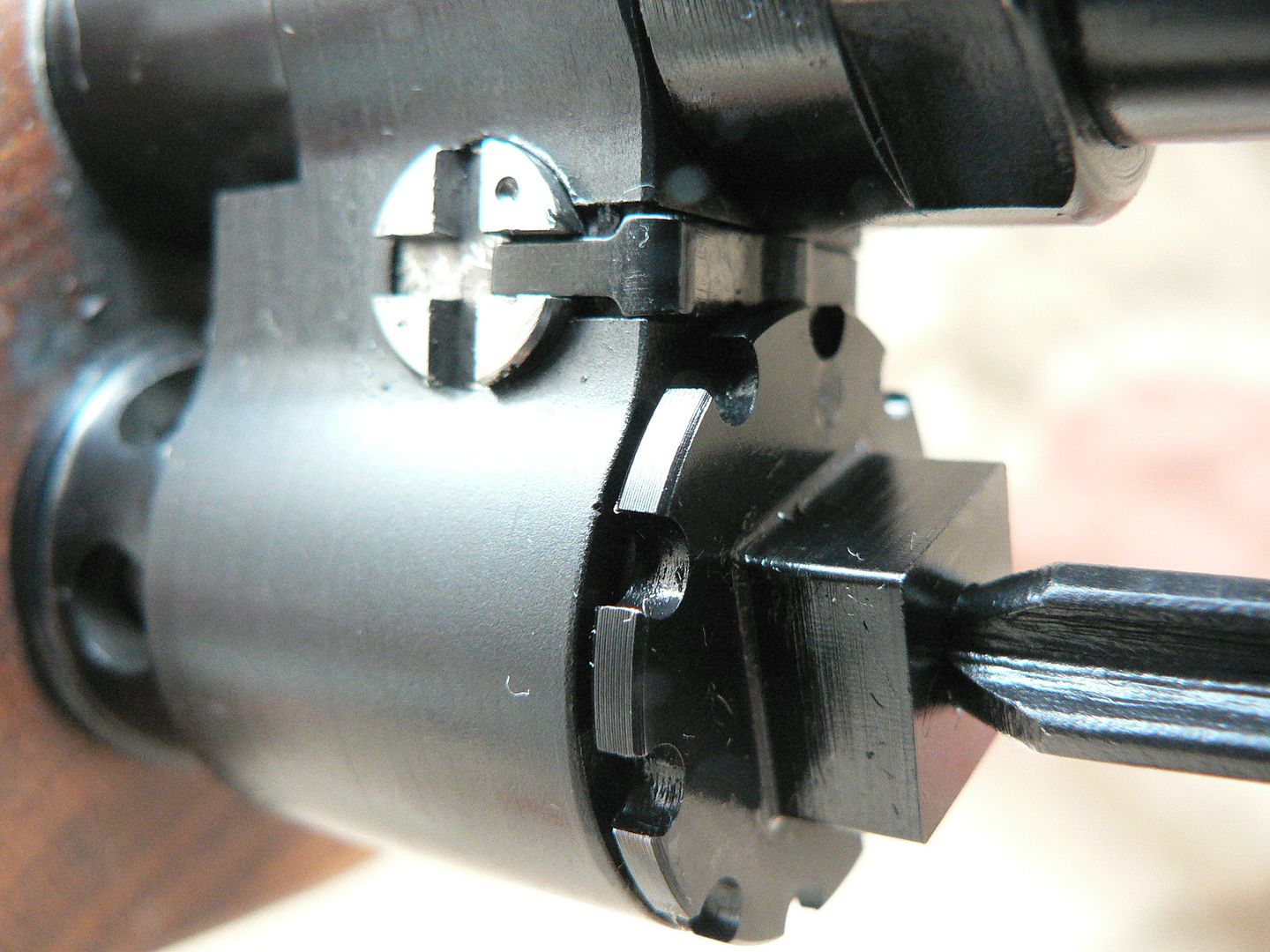 The tip of the bayonet is seen on the lower right of the picture. The reason for this is two fold. First, it helps stabilize the bayonet when stowed. Second, it keeps the shooter from sticking himself while using the rifle. We only want to stick the enemy! Here is a shot of the spike just about to engage the gas plug: 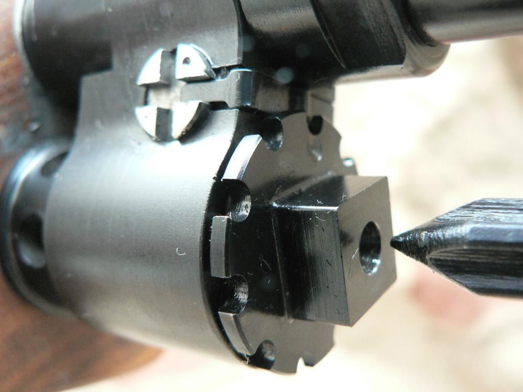 I'm getting a little excited for some reason..... Here is a good close-up shot with the bayonet stowed showing the mounting tube sandwiched between the knurled ring and the front locking nub: 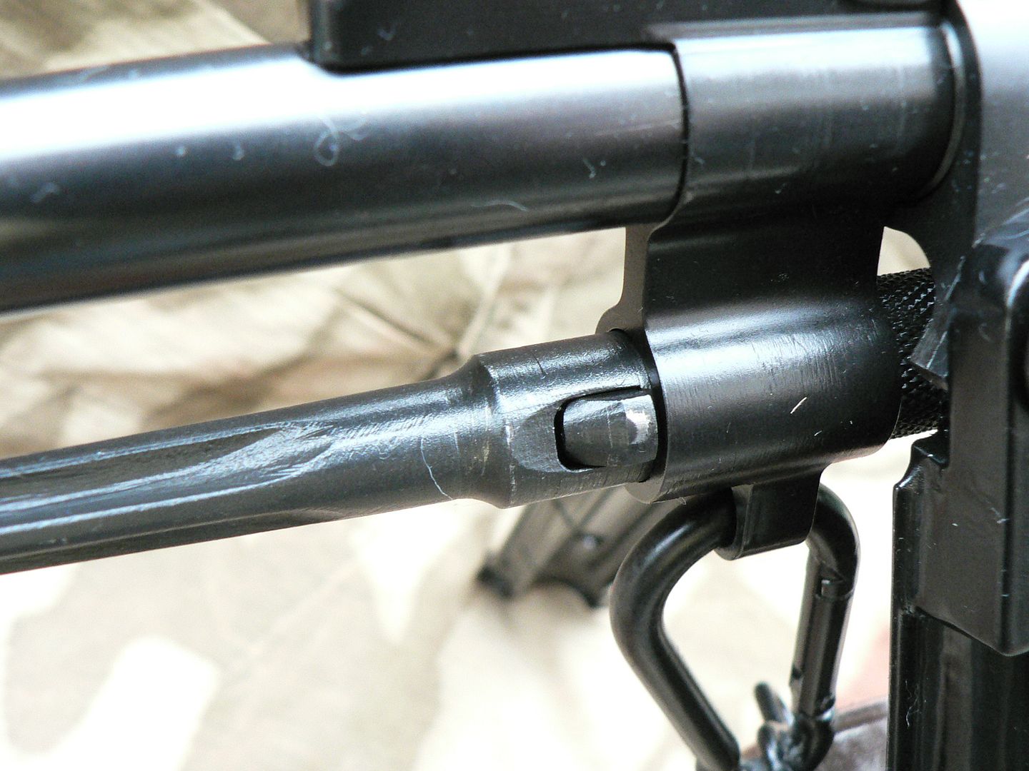 Also of note in the above picture is the sling carabiner affixed to the attachment ring. One last stowed bayonet detail shot showing the rear of the spike protruding out under the muzzle brake: 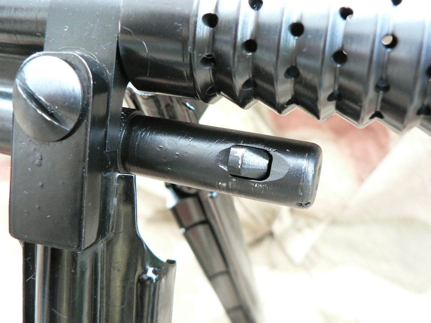 Notice the contrast between the many scratches, dents and dings on the old surplus bayonet compared to the virtually flawless machining on the new muzzle brake. Remember....I love that muzzle brake! It worked so well that the Swiss copied it on their ZFK-55 sniper rifle and used it on many of their prototype weapons in the 50's too. Next up is the bipod. The FG42 was to be a multi-purpose weapon that would replace the submachine gun, rifle and light machine gun. One of the things necessary for it to fulfill the LMG role was a bipod. But being that the rifle was intended for use by airborne troops, it was designed light to save weight. Both proving grounds tests and use in the field proved that it was designed too light and was prone to failure but they kept on making it light anyway. The original was made of pressed steel but remember that SMG doesn't have the capacity to produce stamped parts. To replicate its many contours and details by machining would be neither cost nor time effective. So, SMG decided to outsource the legs (the rest of the bipod assembly is made of steel in shop) and decided on cast aluminum legs made by Shoei, a company that produces a non firing replica of the FG42. Now, if the original stamped steel bipod legs wouldn't stand up to the rigors of combat, I'm sure that I won't be doing push up or drop tests on the aluminum one because I'm sure it would fail. The good news here is that they seem to be plenty stout enough to last a lifetime of noncombat use. It is also notable that the Swiss considered aluminum to be a good enough material for use on the SIG 510, their standard issue battle rifle for approximately 35 years: 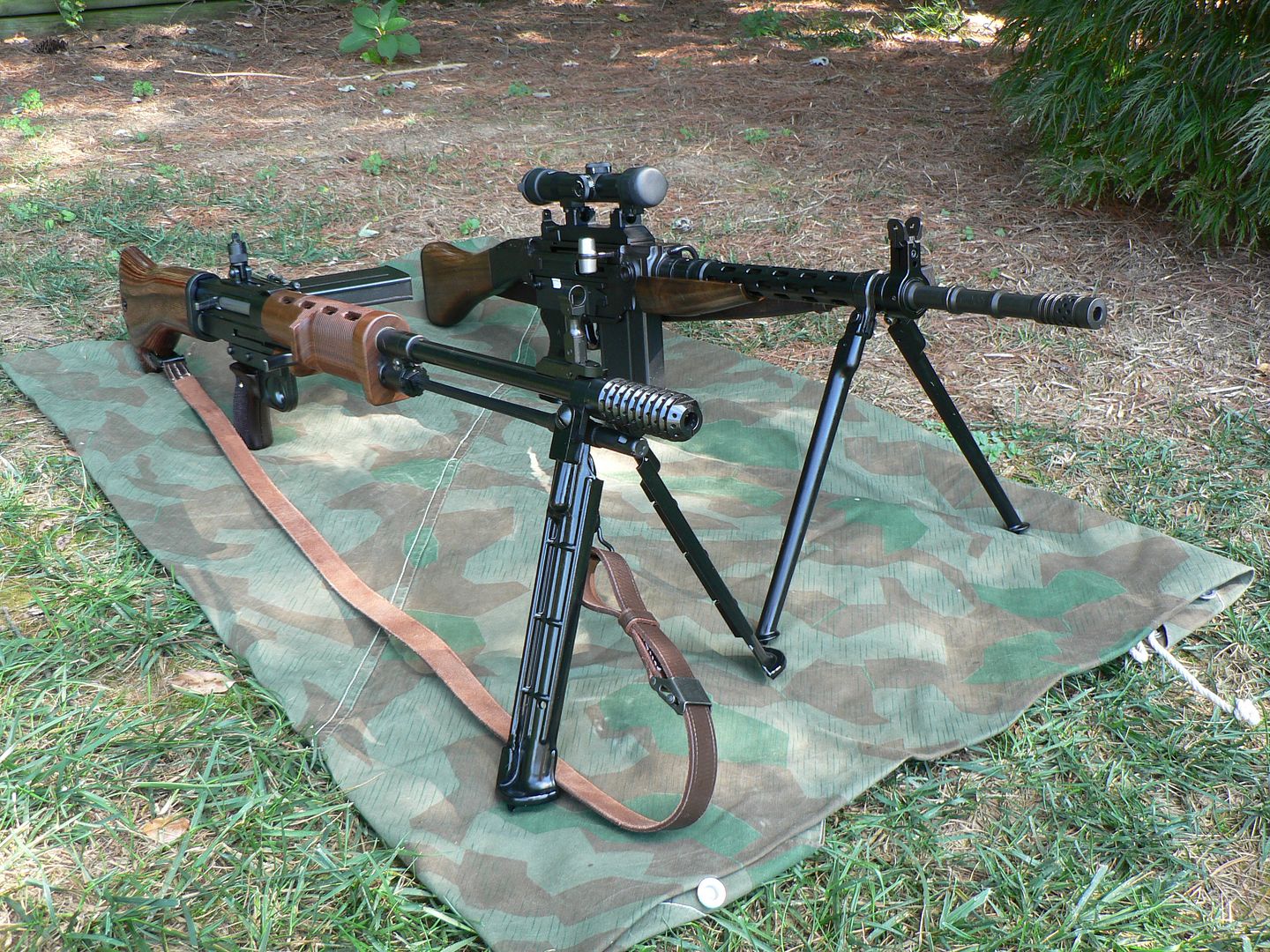 Let's take a look at how the bipod functions by flipping the rifle over and looking at the bottom of the bipod mounting yoke: 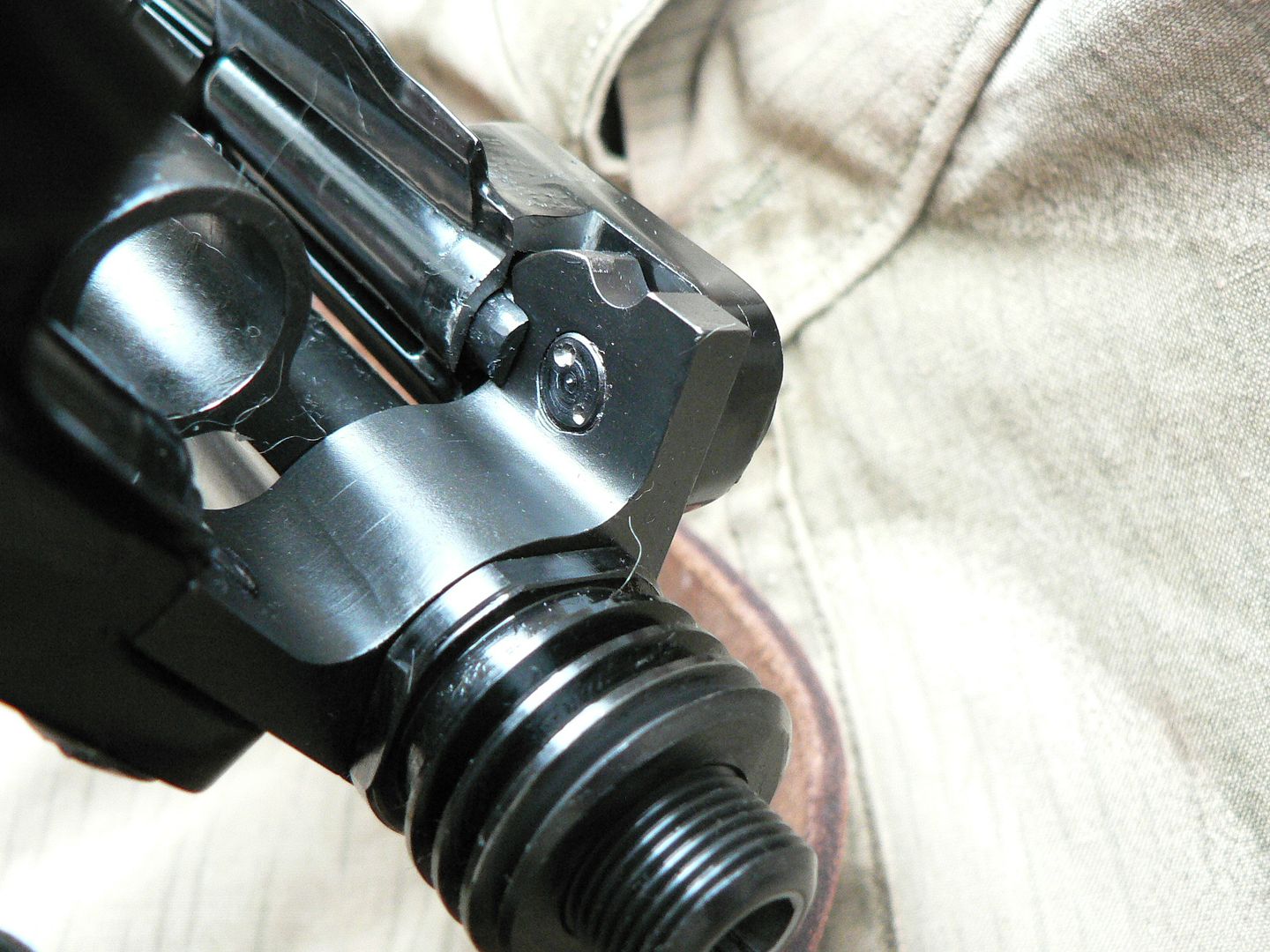 Here we see the right leg stowed and the left one deployed. Notice that the screw which holds the right leg to the yoke is peened in place so that it won't back out. You can see a notch cut in the bottom of the yoke for the spring loaded leg detent to lock into when the leg is folded down and you can see the spring loaded detent currently engaged in a similar notch in the rear of the yoke. Here is another picture showing the right leg deployed: 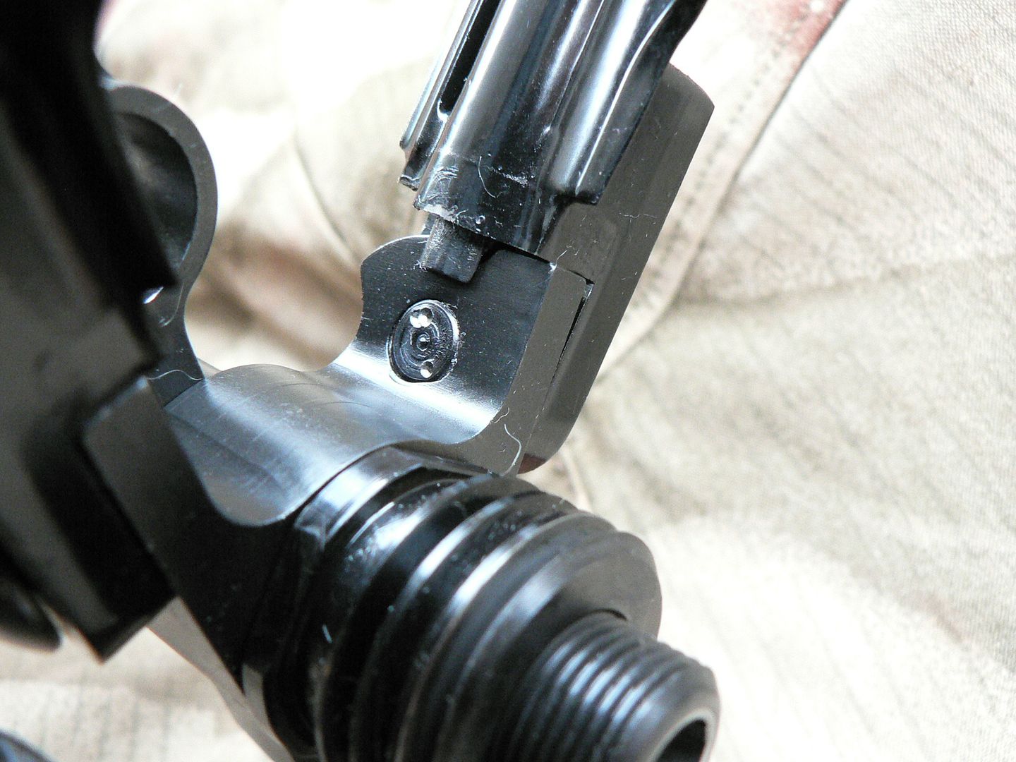 The notch in the rear of the yoke is clearly visible. The bipod yoke will not swing all the way around the barrel, being stopped by the legs hitting against the bayonet mounting tube Moving back the barrel, we come to the gas block: 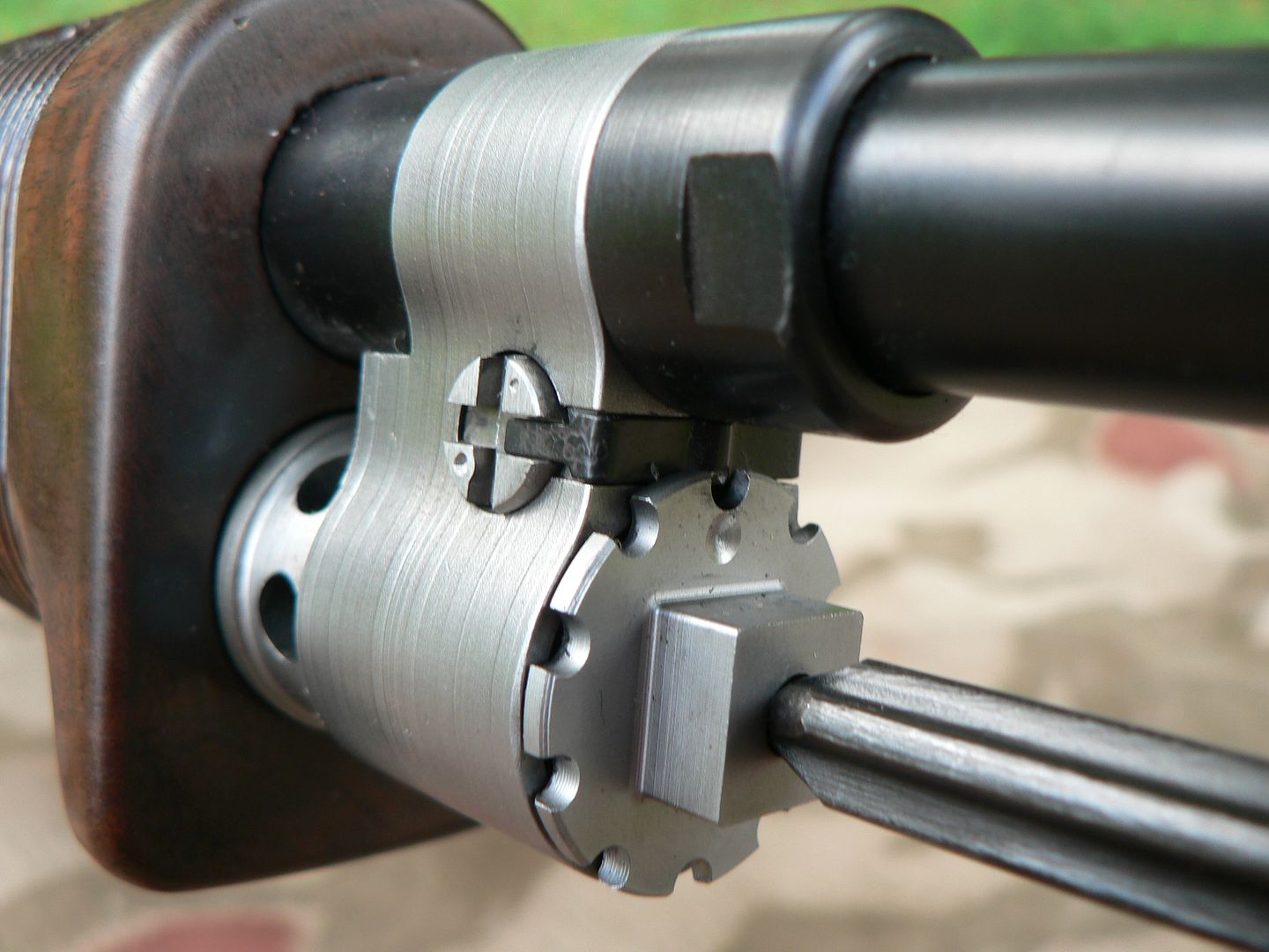 The one shown is not my rifle but belongs to a friend of mine. I chose this picture for two reasons. First, it illustrates that the various parts on the rifle are available in three different finishes. These are blued (barrel and gas block retaining nut shown), phosphate (not shown but of the typical rough textured greenish gray) and bare steel (gas block and gas plug shown). The second reason for choosing this picture is that it makes distinguishing between barrel, gas block and gas block retaining nut a simple task. The barrel has a step machined into it that the rear of the gas block rests against. There is also a flat area on the barrel that is matched by a similar flat area on the block to keep it from spinning on the barrel. The gas block retaining nut is screwed down against the gas block and is held fast by torque and locktite that was pre-applied to the threads. Like the muzzle brake adapter, this is not meant to be disassembled unless you have the proper tools and know EXACTLY what you are doing. So guess what we won't be doing here.... Sticking out the side of the gas block with a "+" cut into it is the stainless steel gas regulator used to adjust how much gas is bled off to cycle the action. We'll take a closer look at that in just a bit. The black strip fitted into one of the regulator slots and wrapping around the front of the gas block is a piece of spring steel called the retaining spring and it serves two purposes. First, it locks the regulator from turning and second, it keeps the gas plug from loosening until you want it too. The gas plug is the crenelated disk on the front of the gas block with the tip of the bayonet sticking into it. It is threaded into the block and is removed for cleaning of the gas tube. Now that we know what's what here, lets switch back to the gas block assembly on my rifle and look at some of the parts in more detail. First, we'll check out the gas plug. To remove it, remove the bayonet. Then fit a wrench over the square lug sticking out the front of the plug and turn it counter clockwise. As you turn, it will click as the crenelations pass over the raised part of the retaining spring. Once it threads out to the point where the retaining spring no longer hits the little notches in the plug, you can turn it by hand until it comes loose. Here's the front of the plug after removal: 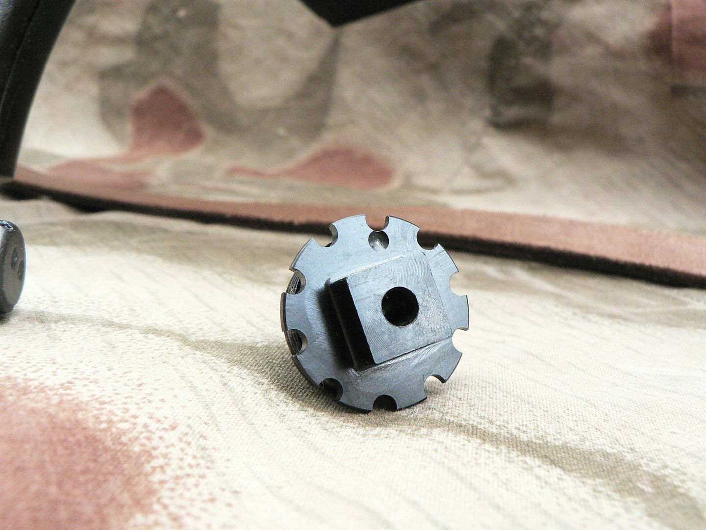 Notice the little dot at the top of the gas plug. This corresponds to a notch cut out of the back shown here at the top: 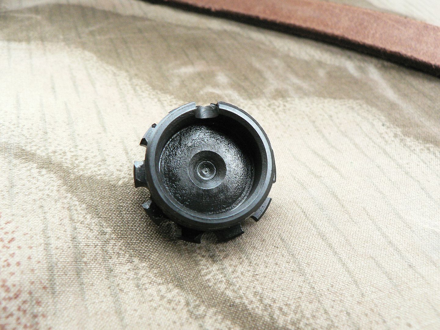 This notch must be aligned with the bottom of the gas regulator upon reassembly so that gas tapped from the barrel during firing can flow into the gas tube and push against the front of the stainless steel piston. If it is not aligned, you will have a single shot rifle because the gas will be effectively turned off. So, when screwing the gas plug in during reassembly, make sure that the dot on the front of the gas plug faces up as shown three pictures above. IMPORTANT: DO NOT crank the gas plug down tight. The dot will be pointing up BEFORE the plug is tight against the gas block. At this point, you will be able to wiggle the gas plug a little bit. That's how it's supposed to be. Here's the side of the gas plug showing the threads: 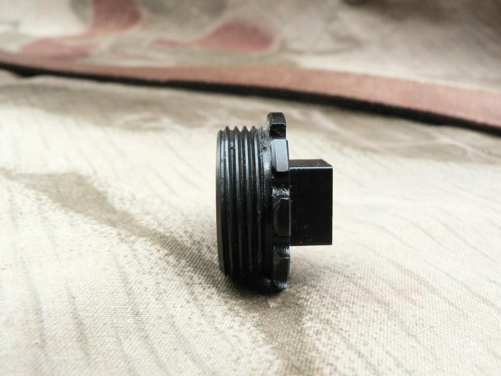 Gas block with plug removed showing the front of the stainless steel piston: 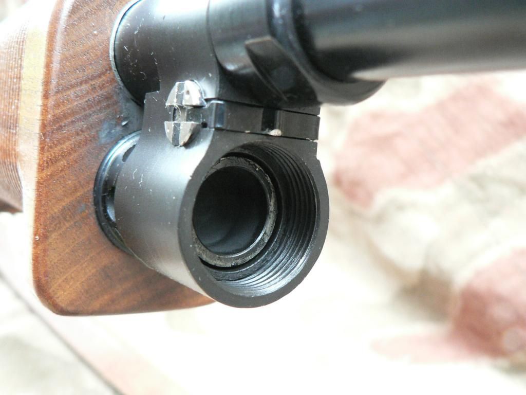 Here's a closer look at the right side of the stainless steel gas regulator: 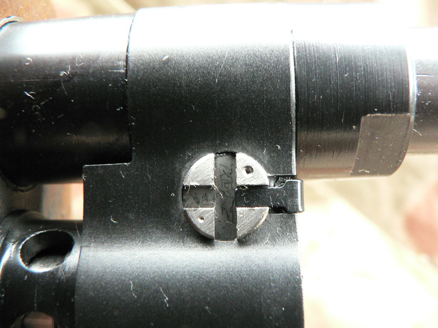 Notice that it has two dimples on it, a large one for more gas(upper right) and a small one for less gas (lower left). Whichever one is positioned on the upper right is the current setting. So, in this case, the regulator is set for more gas (much like me). It should fire on less gas just fine but I haven't tried it yet ( I will be though). To adjust the regulator, the retaining spring must be removed. This is accomplished by pushing the spring forward from the LEFT side of the gas block. Pushing or pulling the spring from the right side WILL damage the spring. So let's look at the left side: 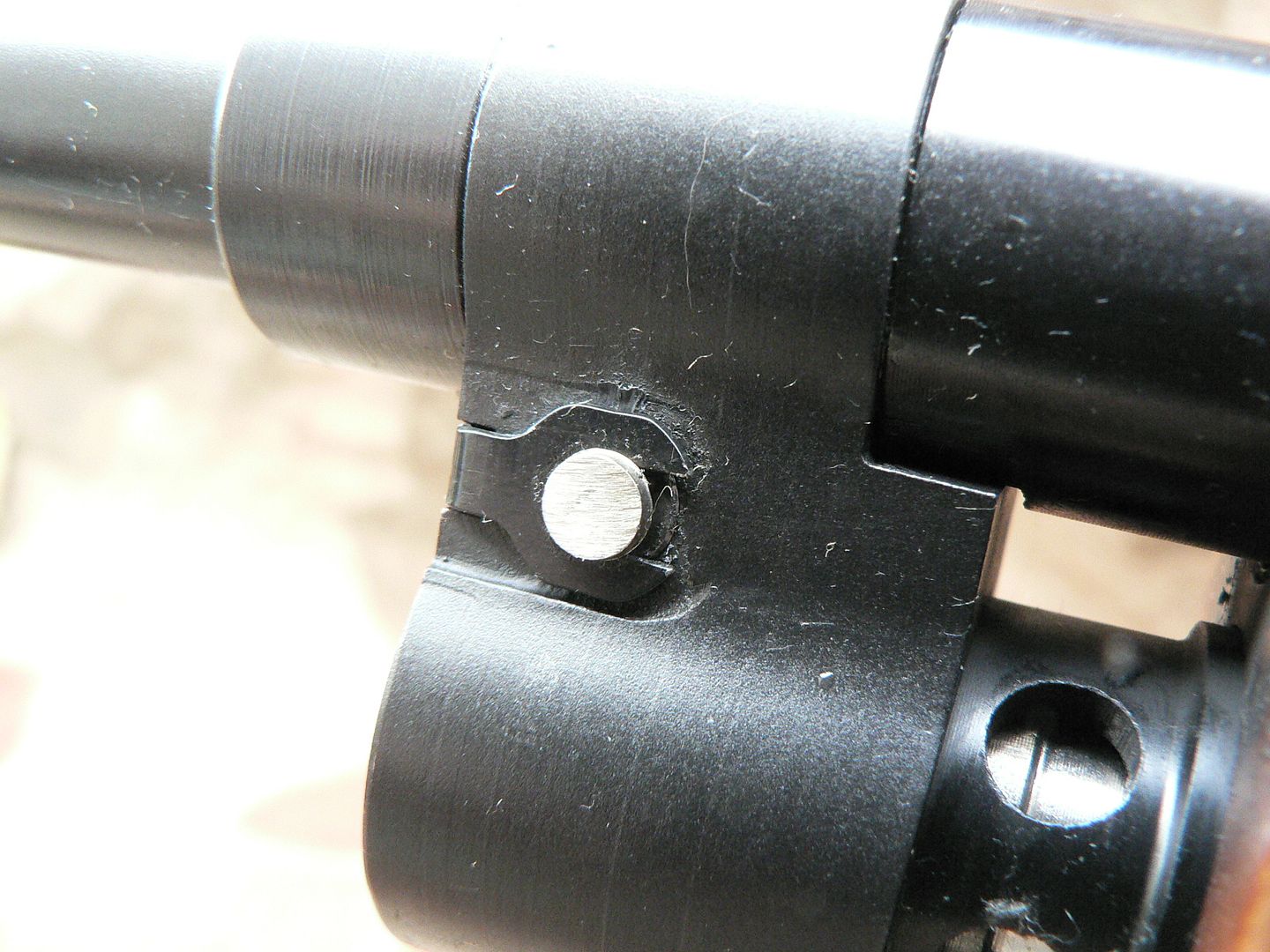 What we're seeing here is the other side of the regulator protruding from the gas block. It has a notch cut into it for the retaining spring to fit into. So, we use a small piece of wood or brass punch (if you are worried about scratching your finish) or a screwdriver/bullet tip (if you aren't worried about your finish) and push the retaining spring forward out of the groove. The manual says to do this with the gas plus partially installed so that you don't push your spring entirely off and lose it but we're taking it completely off here. Once the spring is no longer engaged with the slot on the right side of the regulator, you can insert a screwdriver into that slot and easily turn it where you want it. After setting the regulator, carefully seat the spring by again pushing on the left side. Here's the spring removed from the rifle: 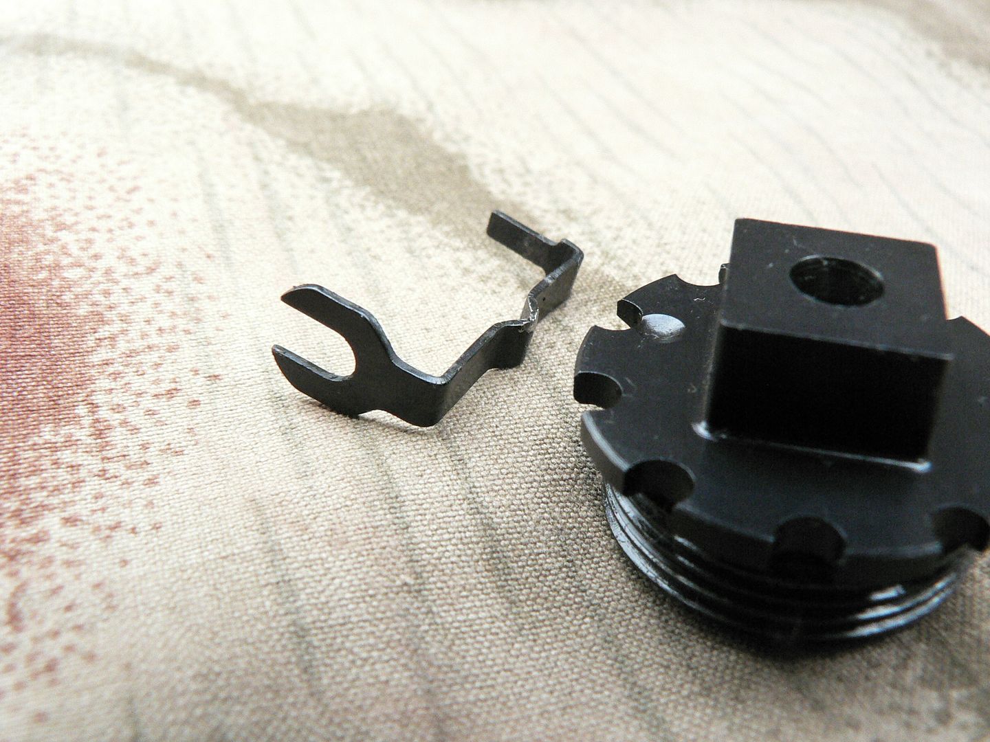 Here's the gas block with the spring removed: 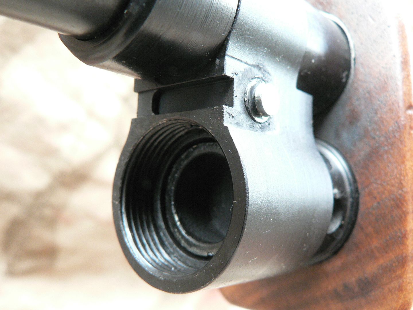 The spring slot has a high and a low area so that the spring seats properly and works reliably. And photobucket decided to die on me so that's it for tonight! I guess I'll try again later.....
__________________
I promise to be nice and play well with others |
|
|
|
| The following member says Thank You to Wilhelm for your post: |
|
09-18-2014, 01:21 AM
|
#6 |
|
User
Join Date: Oct 2007
Location: Maryland
Posts: 340
Thanks: 43
Thanked 107 Times in 51 Posts
|
Finishing up the gas block is a look at the gas ports:
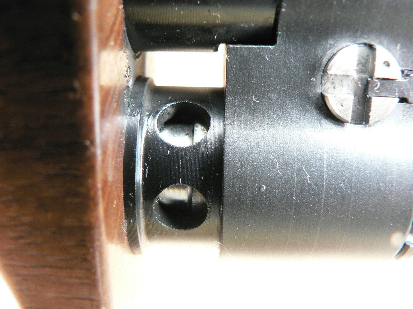 There are two on each side of the rifle and they leave a nice carbon build up on the front of the hand guard! I like that. Through the holes, you can see the stainless steel gas piston and just a little bit of the rear piston ring. Above the gas ports, you can see the earlier mentioned flat area on the barrel that keeps the gas block aligned properly. Here's a shot showing the solid walnut hand guards in both light and dark finishes: 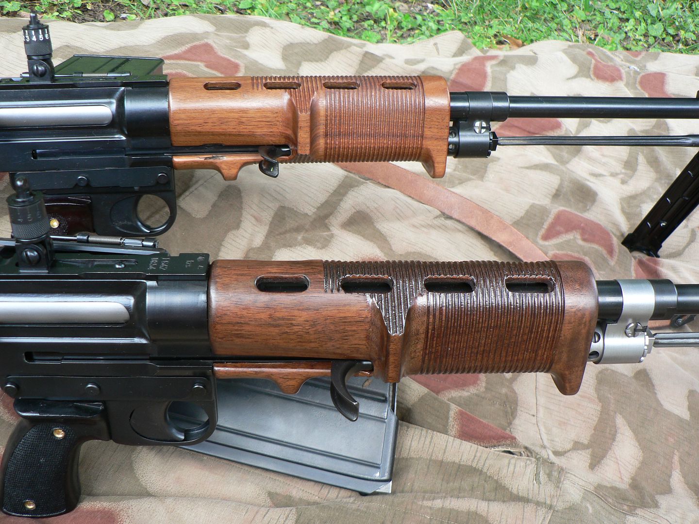 Laminated hand guards are available too are not recommended as they tend to split with use. Inside of the hand guard is a heat shield to keep it from getting too hot. Eight vent holes, four per side, run along the top to help dissipate heat. Here's a close-up showing the grip ridges tooled into the wood: 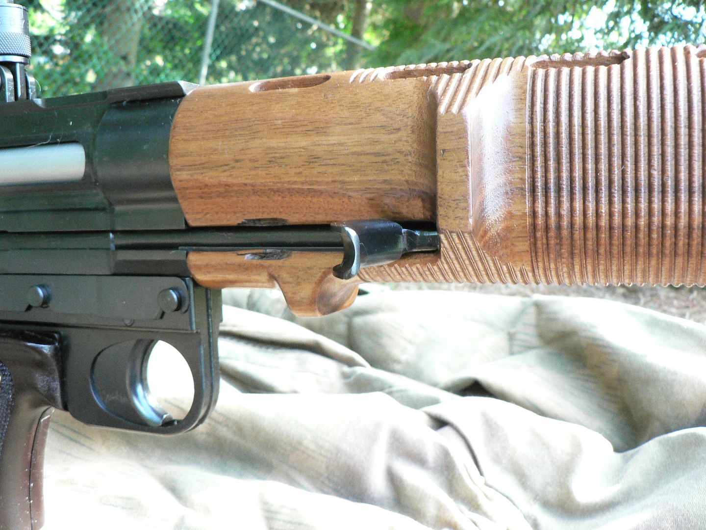 The finish on and detailing of the wood equals the Quality of fine furniture. I've been building furniture for years and couldn't do a better job. Notice the pretty gouges above and below the cocking slot. That's my fault entirely because sometimes I'm pretty stupid. I'll go into greater detail about those gouges when I incorporate the first range trip results into this essay. Next up is the trigger housing assembly. German housings were made of two stamped halves welded together all the way around. The first rifles built by SMG had milled aluminum housings that had a seam applied to them in an effort to make them look more original. They were then painted black. After somewhere in the area of 15-25 rifles, SMG switched to milling them out of two steel halves and then welding them together as originals were. They are currently available with either black or plum plastic grips riveted on as shown here: 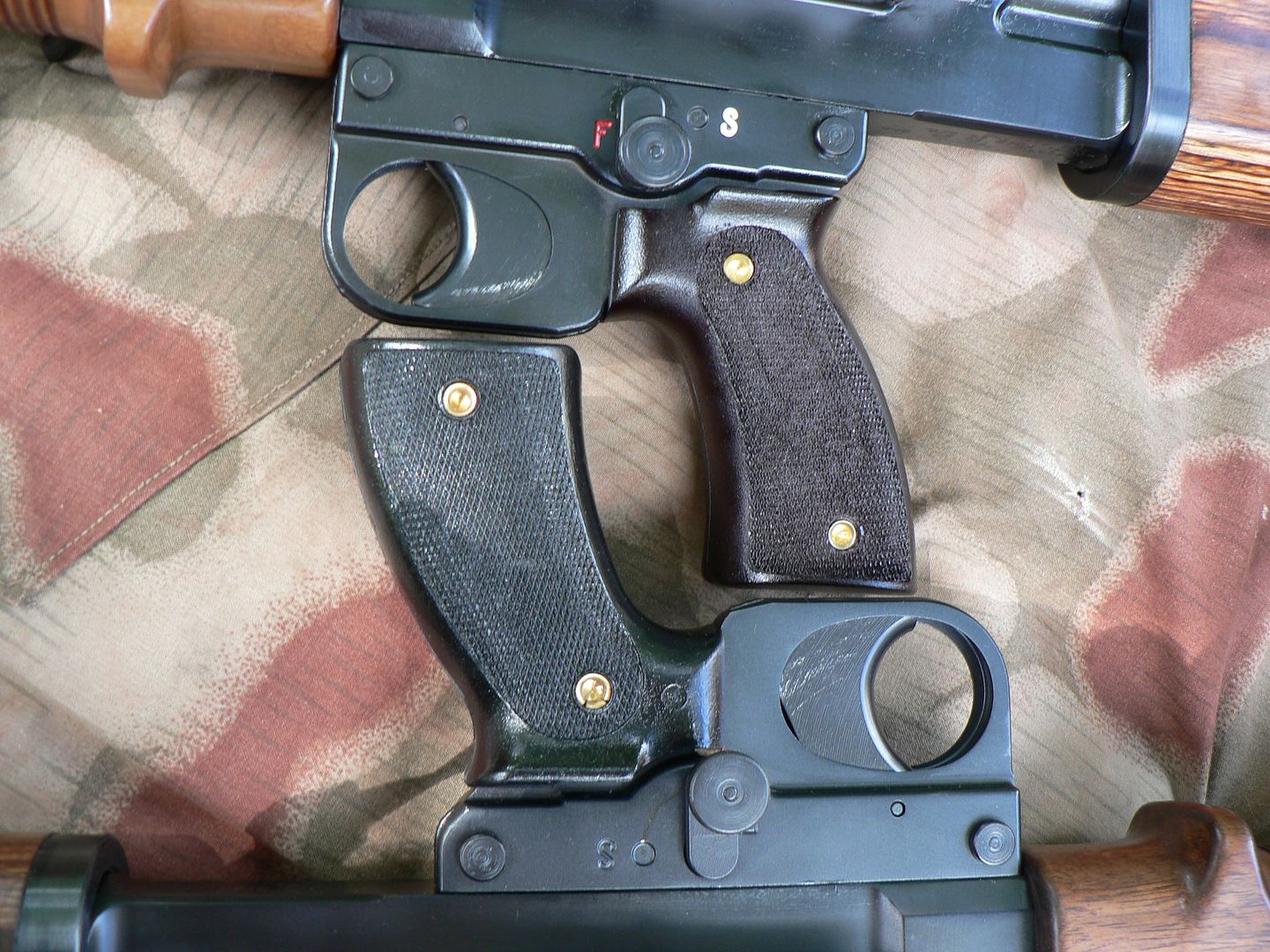 Notice that the upper housing has painted selector marks while the lower one does not. They come unpainted from SMG. I've painted mine and I think the rifle looks more polished with them that way. This rifle has astonishing attention to detail and I don't think that's a detail that should be overlooked (Hint hint). Before we take a closer look at the whole thing, we have to get it off first. This is accomplished by removing the sprung steel plate located on the right side and running the entire length of the assembly: 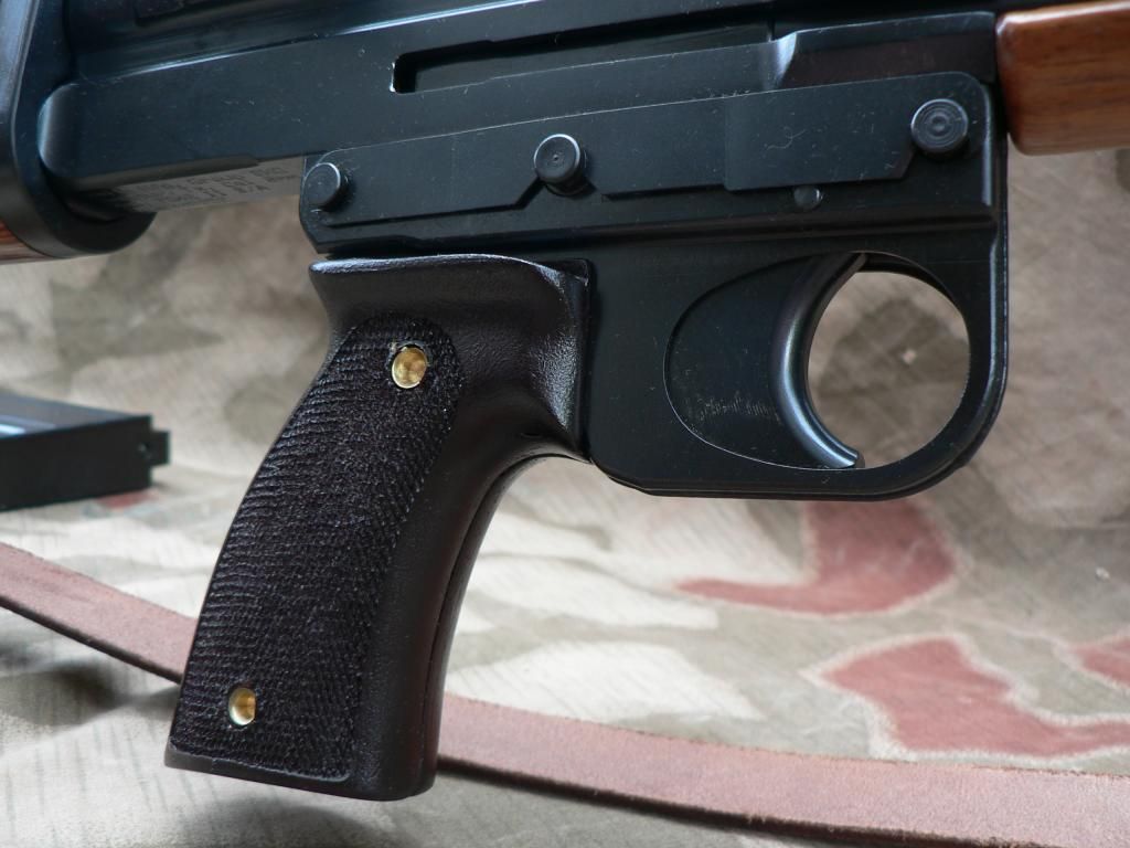 There are four pins seen in the above photo, all of which are held in place by the sprung plate. Starting at the front, we have the front retaining pin. The smaller pin right above the trigger is the trigger pin. In the middle we have the end of the selector axle. And all the way at the back we have the rear retaining pin. To remove the trigger housing, first push up on the front of the plate until it clears the front retaining pin and selector axle: 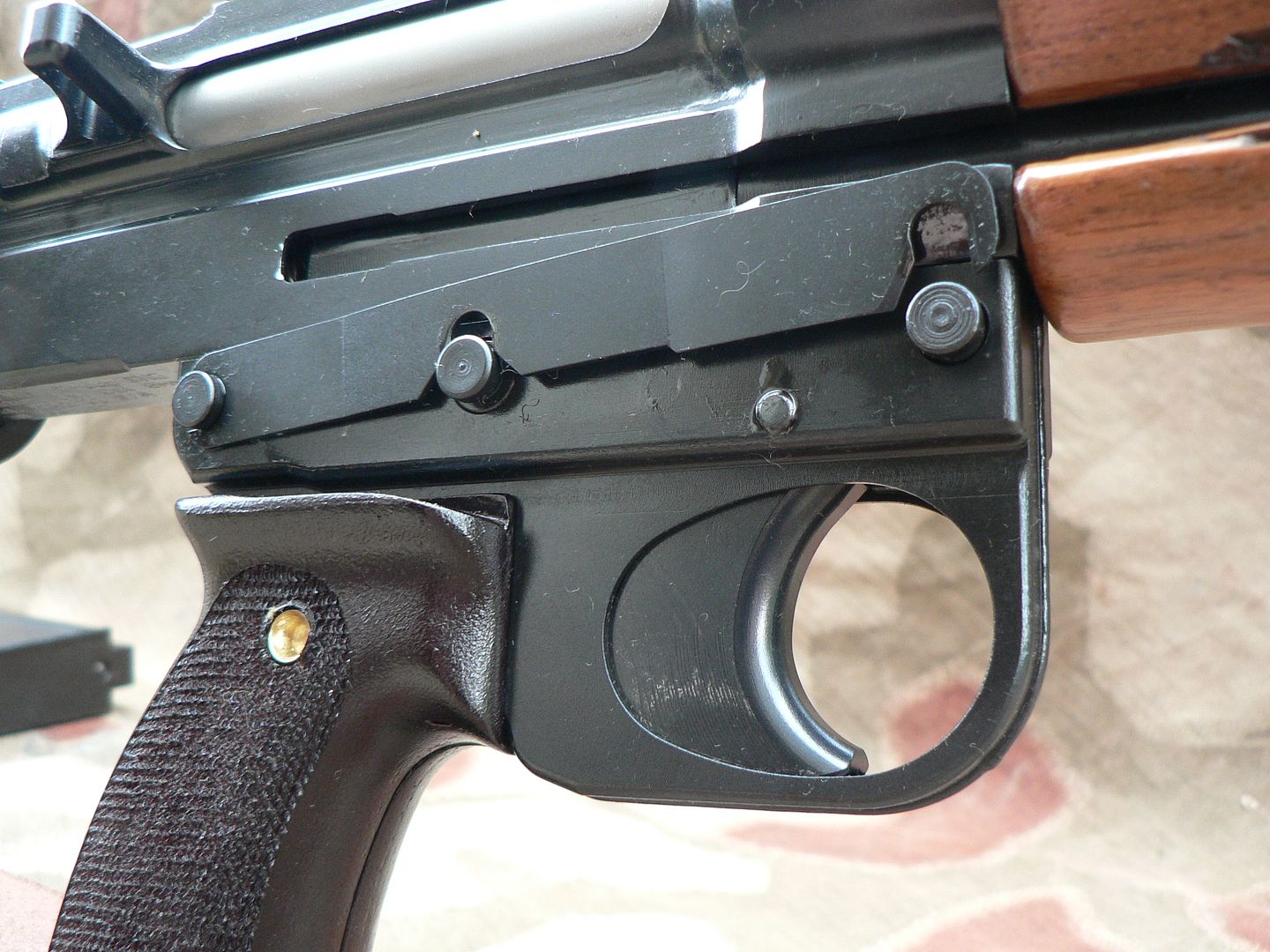 SMG says in their instructional video (included with each rifle) that this part can be vary hard to remove and must be pushed up with a blunt object and some force but mine pushes up with minimal effort using just my finger. It doesn't move during use though so it must lock on well enough. Then pull the plate forward and away leaving it looking like this (looks like I went a little crazy with the CLP there...look at all the oil): 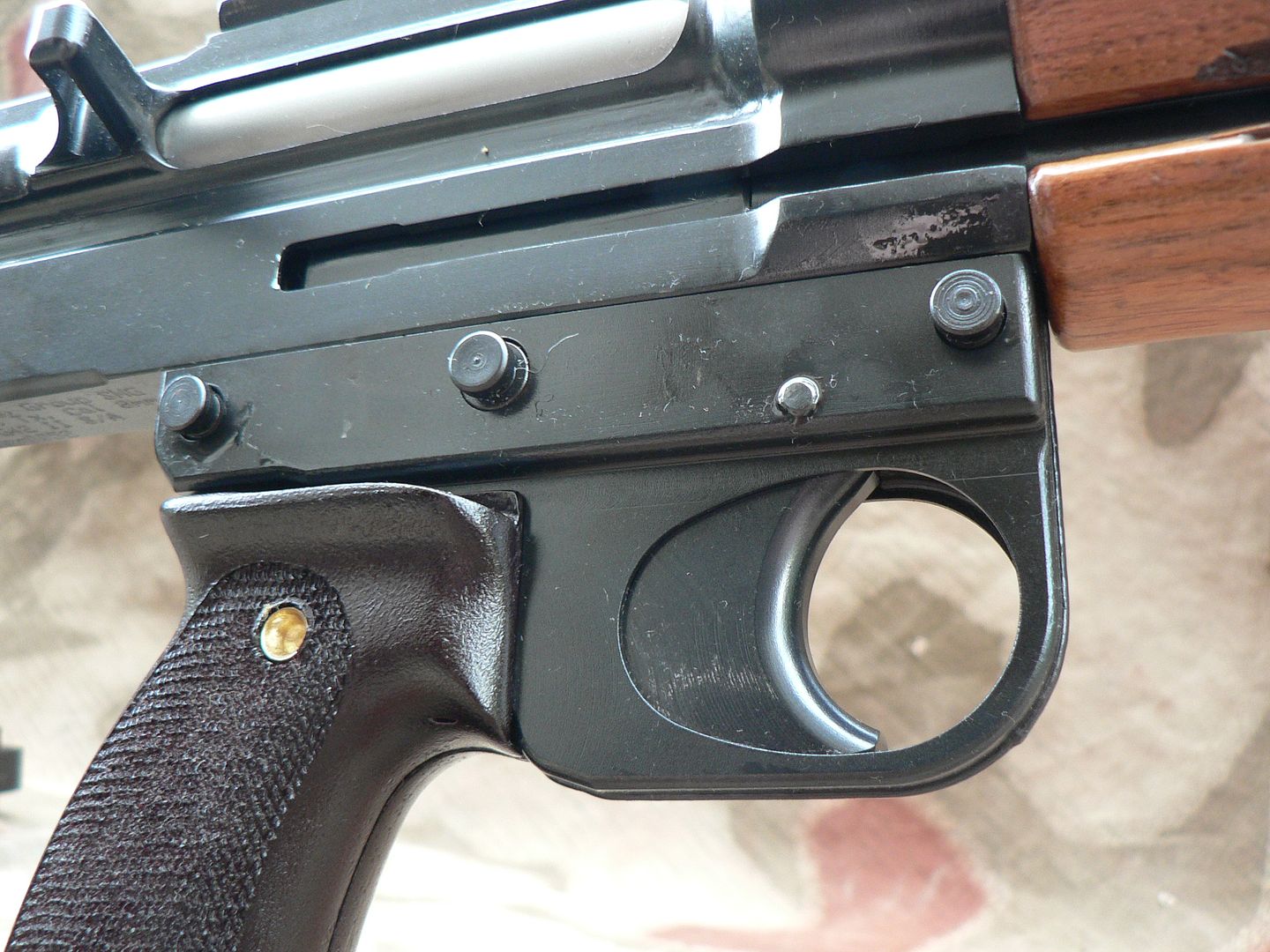 Now push the front and rear retaining pins all the way out from right to left and the trigger housing will simply fall away from the receiver. Here are the retaining pins and locking plate removed from the rifle: 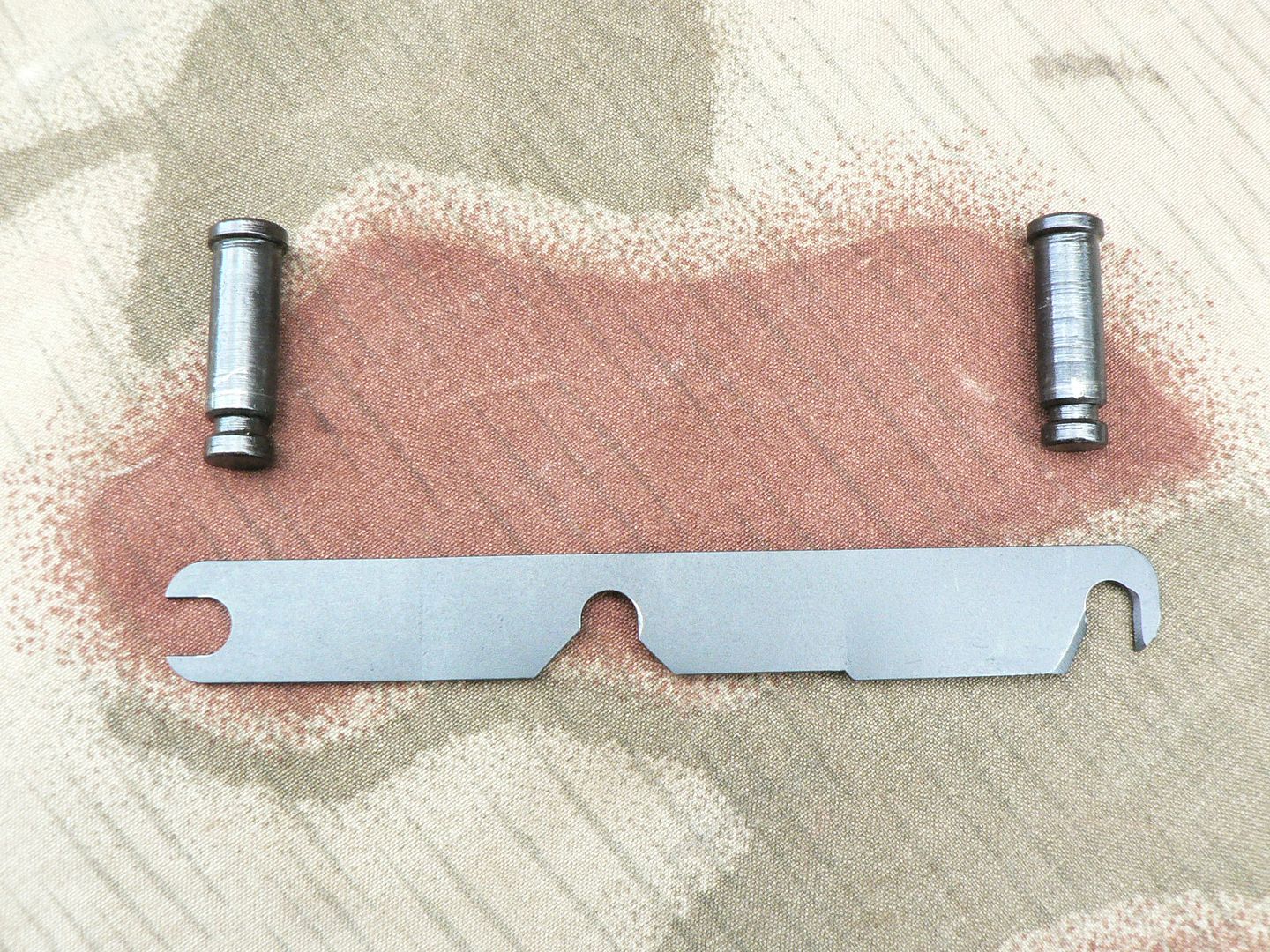 Front is to the right. Both pins are identical and the notches that are engaged by the locking plate are clearly visible. Notice that the front notch of the locking plate has beveled edges. This is done so that it will easily engage with the front pin during reassembly. Original locking plates were removed by rotating them down off the pins. SMG changed the design because they reasoned that the locking plate can't fall off in use if it has to rotate up for removal. I agree 100%.
__________________
I promise to be nice and play well with others |
|
|
|
|
09-18-2014, 03:05 AM
|
#7 |
|
User

Join Date: Feb 2013
Location: Somewhere in Northern Italy
Posts: 2,646
Thanks: 1,082
Thanked 1,783 Times in 1,007 Posts
|
Hi Brian
Goodness you've made such a big and instructive work. Thanks a lot. Sergio
__________________
"Originality can't be restored and should be at the top of any collector's priority list. |
|
|
|
|
09-20-2014, 02:52 PM
|
#8 |
|
User
Join Date: Oct 2007
Location: Maryland
Posts: 340
Thanks: 43
Thanked 107 Times in 51 Posts
|
You are most welcome!
The trigger housing is off. Let's take a look a closer look at it. Here's a view from above looking down into it forward is to the right: 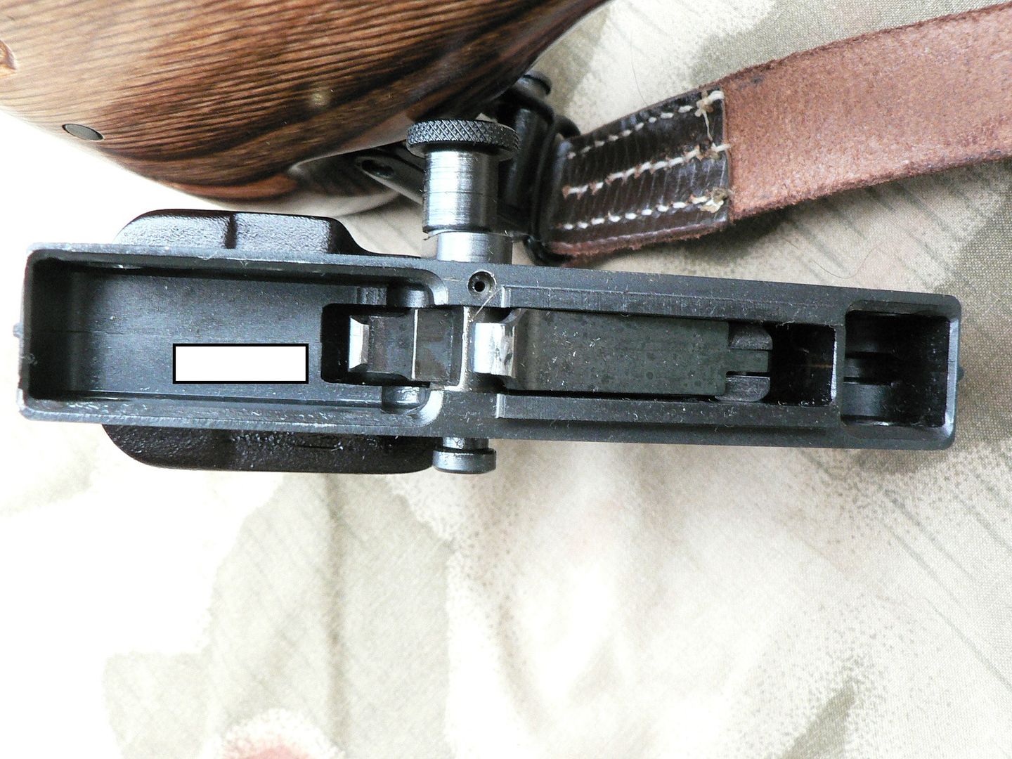 Let's start at the front and work our way back. The first thing we come to is a hollowed out square area. This fits over the front retaining lug hanging from the bottom of the receiver. The front retaining pin passes through the retaining lug. Moving rearward, we come to the fire control group (FCG). All the way to the front of the FCG is the top of the trigger. It has a slot cut into it where the disconnector/sear trip connects to it using a pin. The disconnector/sear trip is one part and it has two lugs sticking up. One is about midway back with the safety axle passing below it and the other is all the way at the rear of the FCG. The lug above the safety axle is the disconnector trip. It is pushed downward as the bolt carrier passes over it, disconnecting the sear trip from the sear and producing semi automatic fire. The rear lug is the sear trip and it pulls forward on the bottom of the sear (mounted in the receiver) as the trigger is pulled. This rotates the sear on its pin and out of contact with a notch in the bottom of the bolt carrier. The bolt carrier then slides forward creating good times and good memories at the range! Behind the FGC is a white rectangle. This white rectangle is where the serial number is etched into the frame but I covered it up. I hated to do that but in todays political climate, and due to the dictatorial state I live in, I feel it necessary unfortunately. All the way at the rear is where the rear retaining lug goes to be captured by the rear retaining pin. The safety is shown in the "F" (Fire) position. To place it in the "S" (Safe) position, the knurled knob is pulled slightly outward and rotated to the rear. This disconnects the FCG from the sear. IMPORTANT: The safety is to be rotated to the "S" position ONLY when the rifle is cocked or the housing is removed from the receiver! It MUST be in the "F" position before the charging handle is pulled to the rear or when the housing is being reattached to the receiver! Failure to follow this advice WILL cause headaches!! The left wall of the trigger housing has a small hole with a black dot in it above the trigger axle. This hole is where the safety axle detent and detent spring are inserted during assembly. The black dot is a hole drilled through the safety axle. I assume that it serves as an oil hole for the detent and its spring but I don't know that to be fact. Now, before you deviants go thinking that all you have to do to convert this thing to fully automatic is grind off the disconnector trip, think again. The geometry of the disconnector/sear trip is such that, when the rifle is fully assembled, it will automatically disconnect itself from the pulled trigger anyways. I'm NOT going to go into how all of that works though. If you look very closely at the above photograph, you can see a faint line in the middle of the grip housing where the two halves meet. It is most noticeable rear of the white rectangle and just in front of the trigger. Fantastic fitting is in evidence here. Let's look at just how well the two halves of the trigger housing are joined: 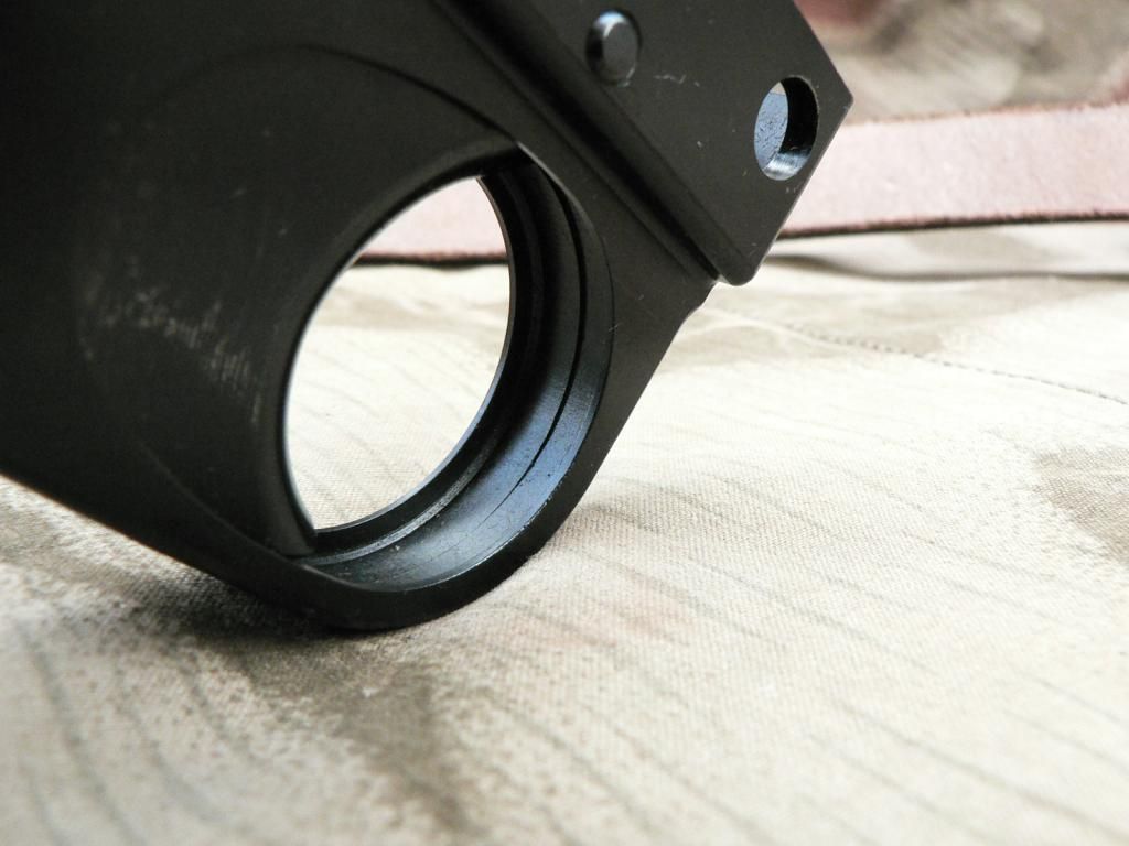 The above picture shows the non-welded side of the seam. Notice that the part of the seam just in front of the bottom of the trigger is flawless. As you go around towards the top of the trigger, the halves do not fit perfectly with one rising above the other creating a ridge. That is NOT a gap but is where the radius of the left half is less than that of the right half. Please do not construe this as a complaint, only an observation. In reality, this area is so small and the ridge so minor that most would never even notice it. It has absolutely no effect on functioning and is cosmetic only. Here is the welded seam on the outside of the trigger housing: 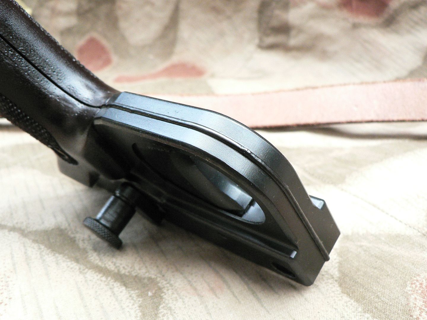 In my opinion, the work is impeccable. If anything, it's TOO good for a reproduction. Here's the whole thing disassembled: 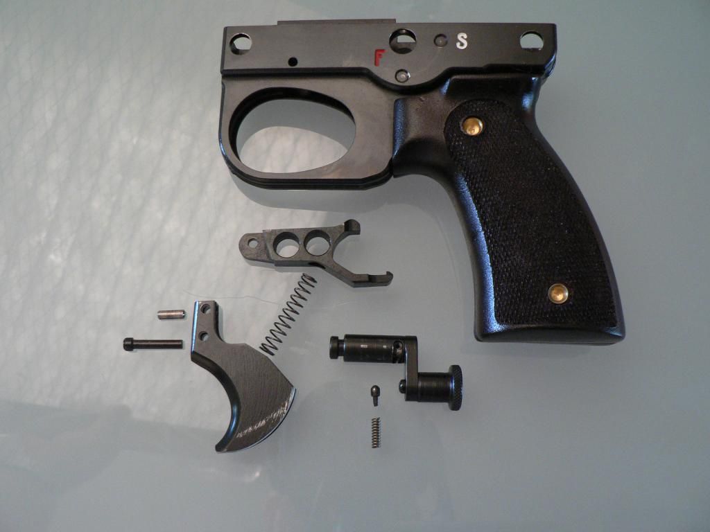 Starting from the top, we have the housing with the disconnector/sear trip below it. This part has three holes in it. The front (left) hole is for the pin that connects it to the trigger. The next two larger holes serve no purpose other than reducing weight (I guess). At the middle top of the part is the disconnector trip. All the way at the rear is the sear trip. Moving down, we have the trigger/disconnector spring. The top of the spring is pointing at the recess in the bottom of the disconnector/sear trip. The spring fits into this recess. The bottom of the spring is pointing to a similar area in the trigger where it fits. In front of the trigger are two pins. The top pin connects the trigger to the disconnector/sear trip. The bottom pin holds the trigger into the trigger housing. To the right of the trigger is the safety. You can clearly see the spring loaded nub that fits into the "F" and "S" recesses on the housing, locking the safety in the desired position. Below the safety is the safety detent and detent spring. To disassemble the trigger housing assembly: 1. Rotate the safety midway between the "F" and "S" positions. 2. Wiggle the safety as you pull it to the left out of its hole in the trigger housing. The disconnector/sear trip will pop up. 3. Remove the trigger spring, safety detent and detent spring. 4. Remove trigger pin by pushing out of trigger housing from left to right. 5. Remove trigger/disconnector/sear trip assembly. These parts can be taken apart by pushing out their pin in either direction. Reassembly is the reverse of the above but be forewarned, it CAN be fidgety to get back together. The entire FCG has been redesigned from what was originally made by the Germans. The original FCG is quite complex with most of that complexity being due to the fact that it was select fire. All of that mess just wasn't necessary with a semi auto only rifle so, this is the result. The less than ideal trigger pull is due to the design of the rifle, NOT the design of the FCG. In a normal system, the only pressure you have on the sear is the relatively weak force of a striker spring or a hammer spring. In this design, we have the force of both a double wound firing pin spring AND a double wound recoil spring to contend with. Both of these springs are trying to push the bolt carrier home but are being stopped by the sear. In other words, there is ALOT of pressure being exerted on the sear. That accounts for the fairly heavy trigger pull. As soon as get a chance to contrast it to the trigger pull in an original (and that IS going to happen) I will report back on that. One last picture showing the area of the trigger where the trigger spring fits: 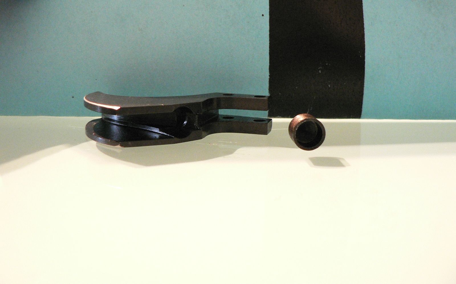 We're looking at the back of the trigger and it's on the left. On the right is a spring cup. This cup fits into the corresponding hole milled out of the back of the trigger. The spring then fits into this cup. Okiedokie, I think that's it it for the trigger housing assembly.....I think. If I forgot anything, I'll get it in the next post!
__________________
I promise to be nice and play well with others Last edited by Wilhelm; 09-21-2014 at 12:52 AM. |
|
|
|
|
09-26-2014, 02:51 AM
|
#9 |
|
User
Join Date: Oct 2007
Location: Maryland
Posts: 340
Thanks: 43
Thanked 107 Times in 51 Posts
|
I've been busy so I haven't been posting. I'm still busy but I'm going to do at least a short post this evening.
Let's start looking at the receiver. On original rifles, this part was stamped. SMG mills theirs out of an approximately thirteen pound block of steel, ending up with a finished receiver that weighs right around two pounds. When seen from that perspective alone, it's easy to see why the Germans stamped them out of sheet metal! I can't even imagine how much time and how many individual cuts goes into machining each one. If I'm reading the manual and the rifle itself properly, there is a trunnion pressed and pinned into the receiver shell that contains the cutouts for the two locking lugs on the bolt. The barrel also screws into the trunnion. Lets, start by looking at the right side of the receiver:  To the right of the above picture, you can see the rear of the walnut hand guard. At the bottom of the picture you can see the top of the trigger housing and its retaining pins. Above the trigger housing is the cocking slot. The rear of the slot is enlarged to (supposedly) facilitate removal of the charging handle during disassembly of the rifle. I say "supposedly" because it isn't necessary. The cocking slot is wide enough for the charging handle to be removed anywhere throughout its entire length. In other words, the enlarged area is pointless. The bulged area at the front of the receiver is where the trunnion is located. If you look very carefully, you can see a little less than half the diameter of the trunnion retaining pin. The rest of it is hidden by the hand guard. This pin is very well fitted to the receiver so its a little hard to see but it's there. Behind the trunnion bulge is the ejection port with the bolt visible through it. Behind the ejection port is the case deflector which helps with positive and reliable ejection. It's welded in place on the receiver but some of the earlier rifles had this part pinned in place. We'll look at that in just a minute. Riveted in two places to the top of the receiver is the rear sight plate. It's dovetail shaped so that it also serves as a scope rail. At the base of the rear sight is a slotted screw. Original rifles simply had a pin here which served only to attach the rear sight to the rifle. SMG has improved on the design by making the rear sight windage adjustable using this screw. Turning the screw clockwise moves the sight to the right. Turning the screw counter-clockwise moves the sight to the left. Similar to the front sight, the rear sight folds down. But instead of a detent and spring arrangement, it uses a leaf spring to hold it in either the up or down position. This leaf spring is retained by the front sight plate rivet. Here's a picture of the rear sight folded : 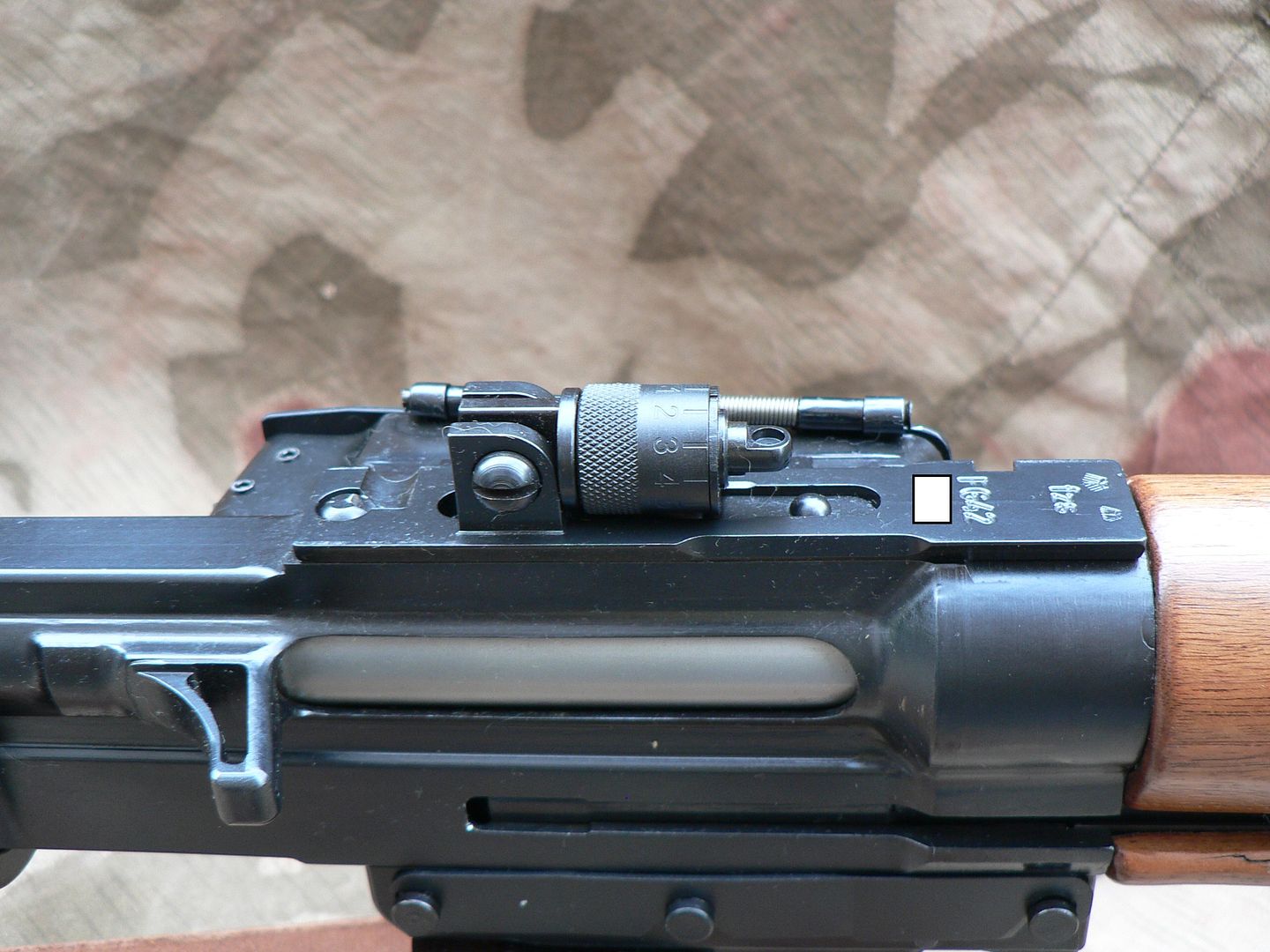 Let's look more closely at both types (welded and pinned) of case deflectors. Here's a close-up of the later welded type deflector: 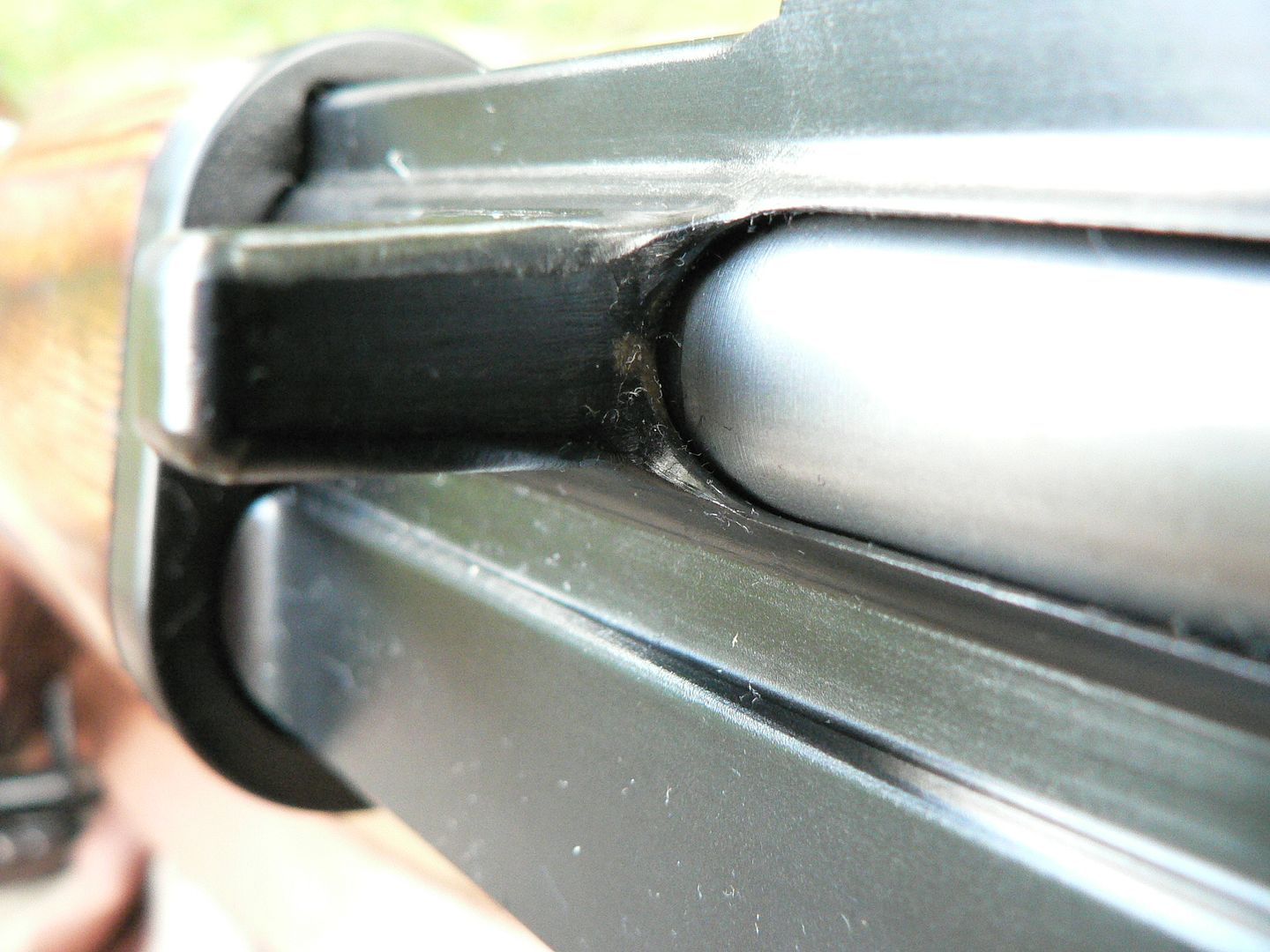 The ejection port is to the right of the picture. I can only assume that there is a dovetail underneath of that weld based on what an earlier pinned deflector looks like as seen here: 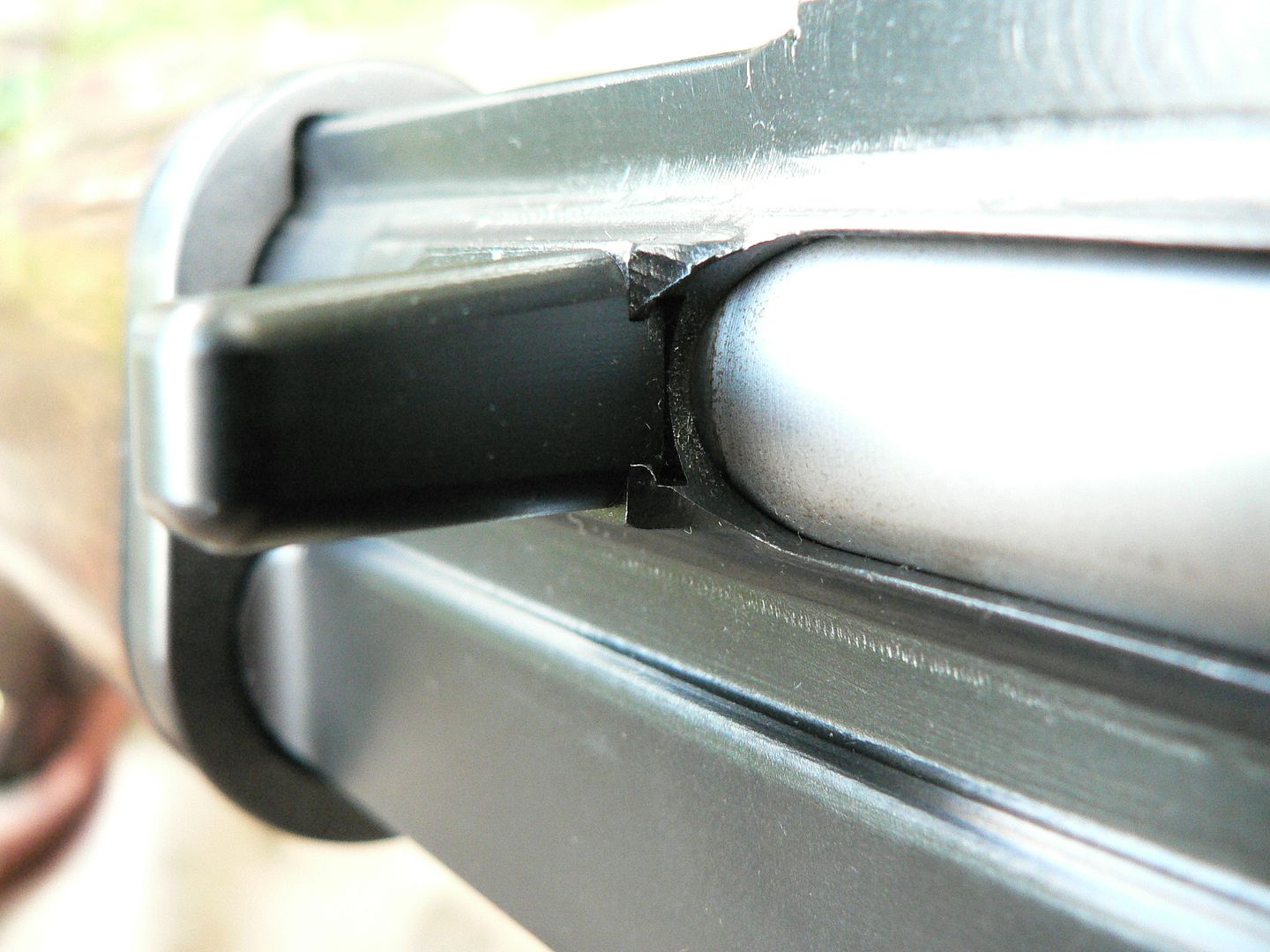 In this view from underneath, the retaining pin hole for the earlier deflector is clearly visible: 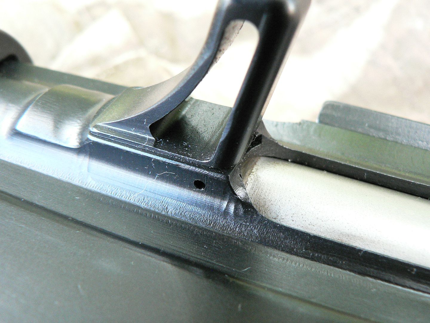 This photo shows a top view of both deflector types: 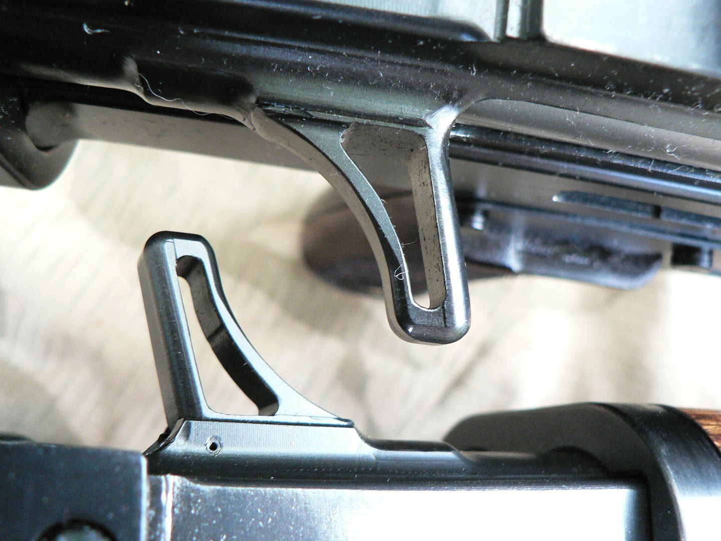 The pinned deflector is at the bottom and the retaining pin can be seen. Before continuing on with the rest of the receiver, let's take a closer look at the rear sight. Here's what the sight looks like set to the 100m position: 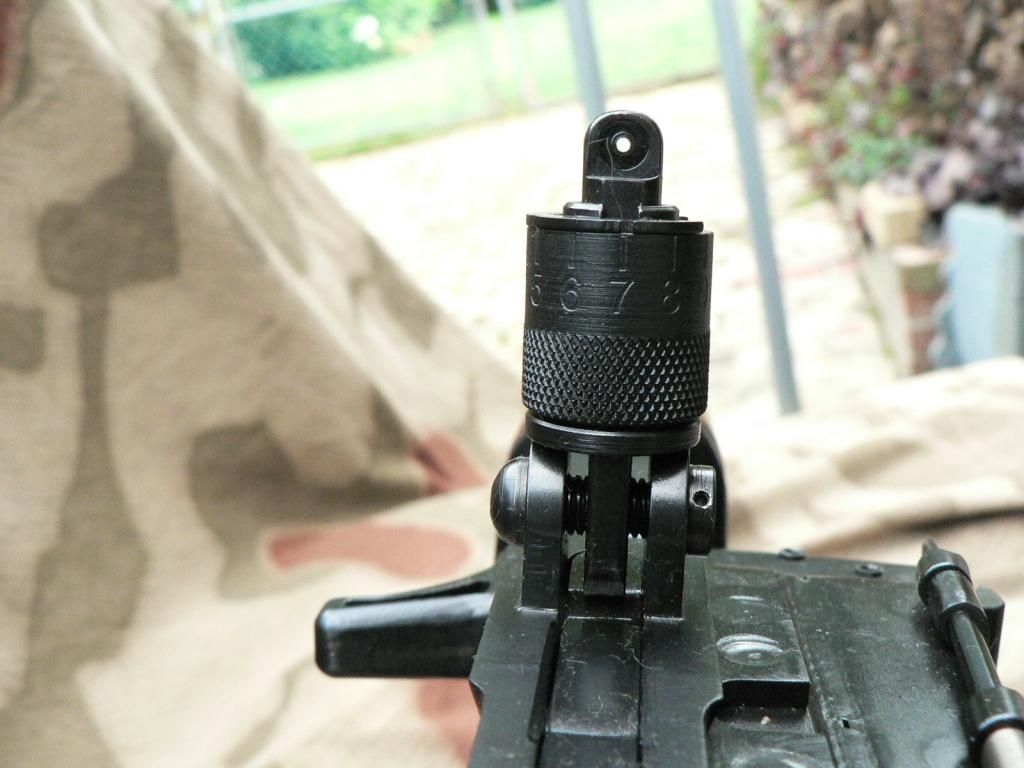 We are looking from the front of the rifle towards the rear. This shot nicely shows the windage adjustment capability of the sight. The nut on the end of the adjustment screw is pinned to the screw. The sight base is NOT threaded so the screw just turns in place without moving right or left as you turn it. Only the rear sight itself moves left or right. All of this is pretty closely fitted so that the adjustment doesn't change during recoil or as you fold the sight up or down. It only turns when you use a screwdriver. That's Quality! To adjust elevation on the rear sight, simply push down on the aperture post sticking out the top and spin the knurled range barrel until the range you are shooting at is displayed at the center rear of the sight. Then release the aperture post and the range barrel will lock in place. Settings are from 100-1200m in 100m increments. DO NOT try to turn the range barrel unless the aperture post is pressed down or you can damage the rear sight! Here is the sight set to 1200m: 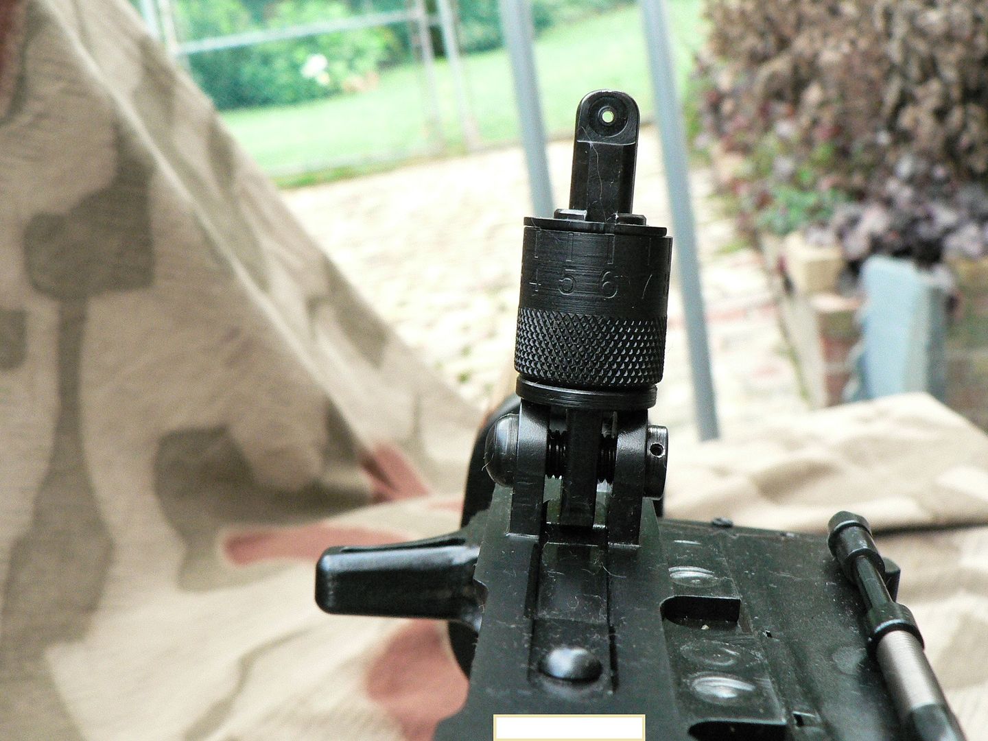 Notice how much higher the aperture post is at this setting. This view also shows the sight leaf spring pressing up against the bottom of the sight and the rivet holding the spring to the rear sight plate. Here's a left side view of the sight folded showing the adjustment screw retaining nut: 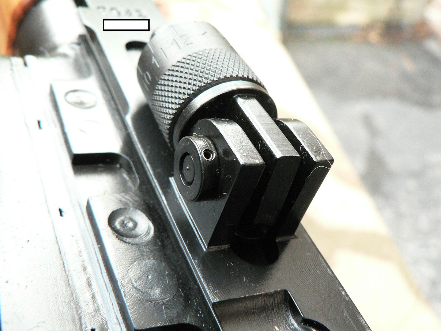 Notice how fine the knurling is on the sight and how crisp the lines are on the various edges and contours of parts. Also, note worthy is how well it all goes together. In my opinion, anyone who questions why these rifles cast as much as they do really has no idea what kind of care and skill goes into crafting a product such as this. If it's not as well built as my SIG (and it just might be), it's so close that any difference is negligible. Having said that.....PLEASE SMG, engrave the elevation markings a little deeper and paint them prior to the rifle leaving your facility. Which looks better and is easier to read? This? 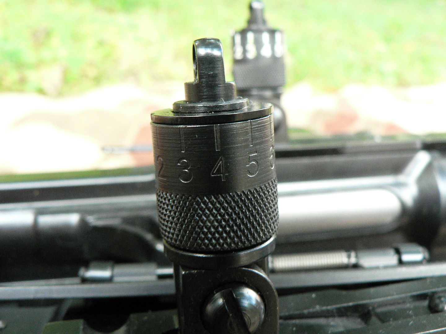 Or this? 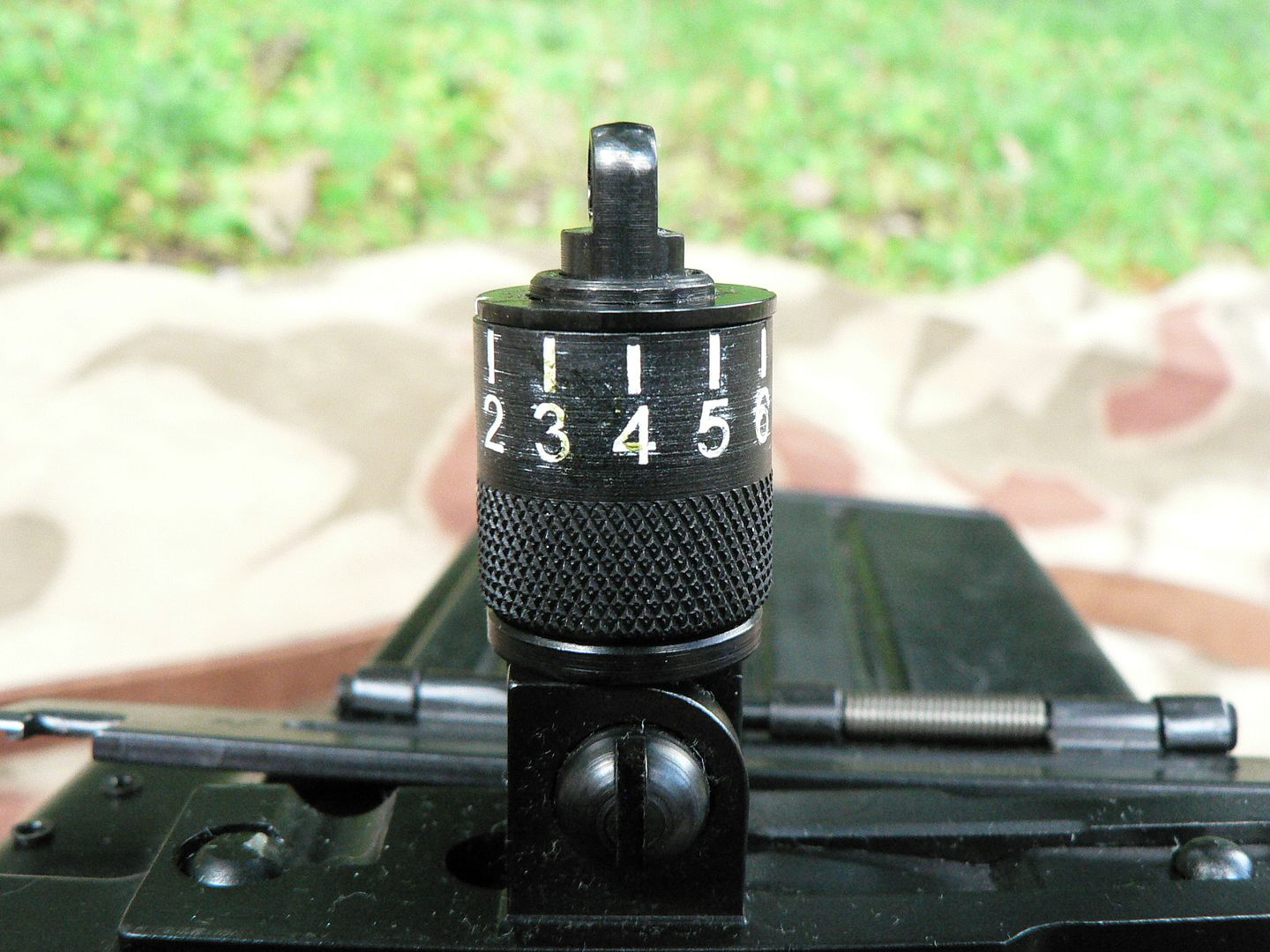 It would look even better if the engravings were deeper so that I could more aggressively remove the extraneous paint from the imperfections in the steel without pulling the paint from the numbers and indices. In the next post, we'll stay with the receiver; starting with moving up to the top and discussing the rear sight plate before working our way around to the right side and bottom. Thanks for your time and please keep checking back for more!
__________________
I promise to be nice and play well with others Last edited by Wilhelm; 09-27-2014 at 02:46 PM. |
|
|
|
|
09-27-2014, 02:01 PM
|
#10 |
|
User
Join Date: Oct 2007
Location: Maryland
Posts: 340
Thanks: 43
Thanked 107 Times in 51 Posts
|
We left off at the top of the receiver. So let's get a picture of that up and I'll tell you what I know about it and what I don't know too.
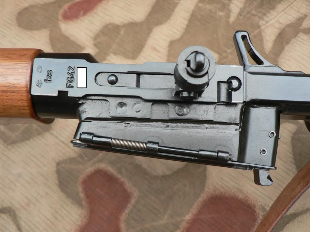 Front is to the left and the magazine well is at the bottom of the picture. All the way at the front of the rear sight plate are two stylized eagles. On original rifles, these were the Luftwaffe acceptance stamps. They were put there to show that the rifle had been inspected and accepted for service by the Luftwaffe. Unlike typical German firearms that are covered with acceptance stamps on almost every single part, the FG 42 was almost devoid of markings other than those seen on the rear sight plate. On the SMG FG42, those stamps are put on there just for the fun of it. You simply CAN NOT have a rifle, whether it be German or a copy thereof, without an eagle somewhere! Behind the "acceptance" stamps, are the pantographed letters "fzs". During the war, that was the manufacturing code for Kreighoff. Again, they are put on this rifle for historical purposes. If you prefer, you can have "SMG" placed in this area which, of course, would be more accurate. Moving rearward, we see the front rivet that holds the plate to the top of the receiver and holds the leaf spring for the sight in place too. Then we have the rear sight in the deployed position. Behind that is the rear rivet. Just in front of the rivet is a dished out area which actually cuts away part of the rivet. This is used to position the optics in the proper place for eye relief and to keep them from moving forward during recoil. It is engaged by a cam on the tensioning axle of the rear scope ring. We'll look at all of that later when we get to the optics. To the immediate left of the sight plate are a couple of tabs, each of which has two spot welds. The purpose of these tabs is unknown to me. Whether they are part of the sight plate and are used to help hold it in place or were put there simply to mimic the look of an original rifle I do not know. What I do know is that the welds are real as is evidenced by the fact that they look different on different rifles as seen here: 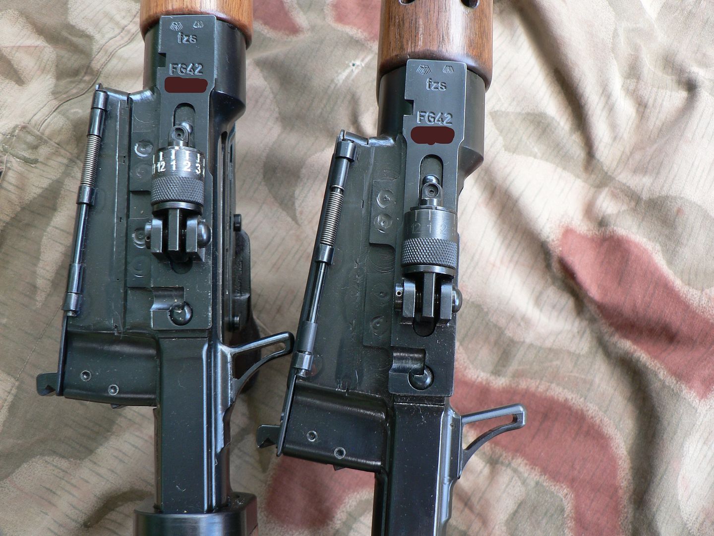 It's hard to tell exactly what's going on where the various parts meet because the joints are so well executed (that's a good thing). Whatever the case, I assume that they do serve some purpose and are not purely cosmetic. Let's get back to the first picture: The magazine well is a separate machined part that is welded to the receiver all the way around and on the inside too. It is "L" shaped with the base of the "L" towards the rear. If you look closely, you can see the weld line. The base of the "L" has two pins in it. The outboard and forward pin holds the magazine catch in place while the inboard rear pin holds the ejector in place. Both are mounted inside the magazine well so we can't see them here of course. Between the magazine catch and the ejector is a spring. It serves two purposes. First, it acts as the tensioner for the magazine catch. Second, it acts as the tensioner for the ejector which rotates out of the way when the bolt moves forward and snaps back into position as the bolt travels rearward so that it can eject the empty casing. We can see the back of the ejector if we look at the back of the magazine well. Here, the bolt is to the rear and the ejector is in position ready to eject a casing: 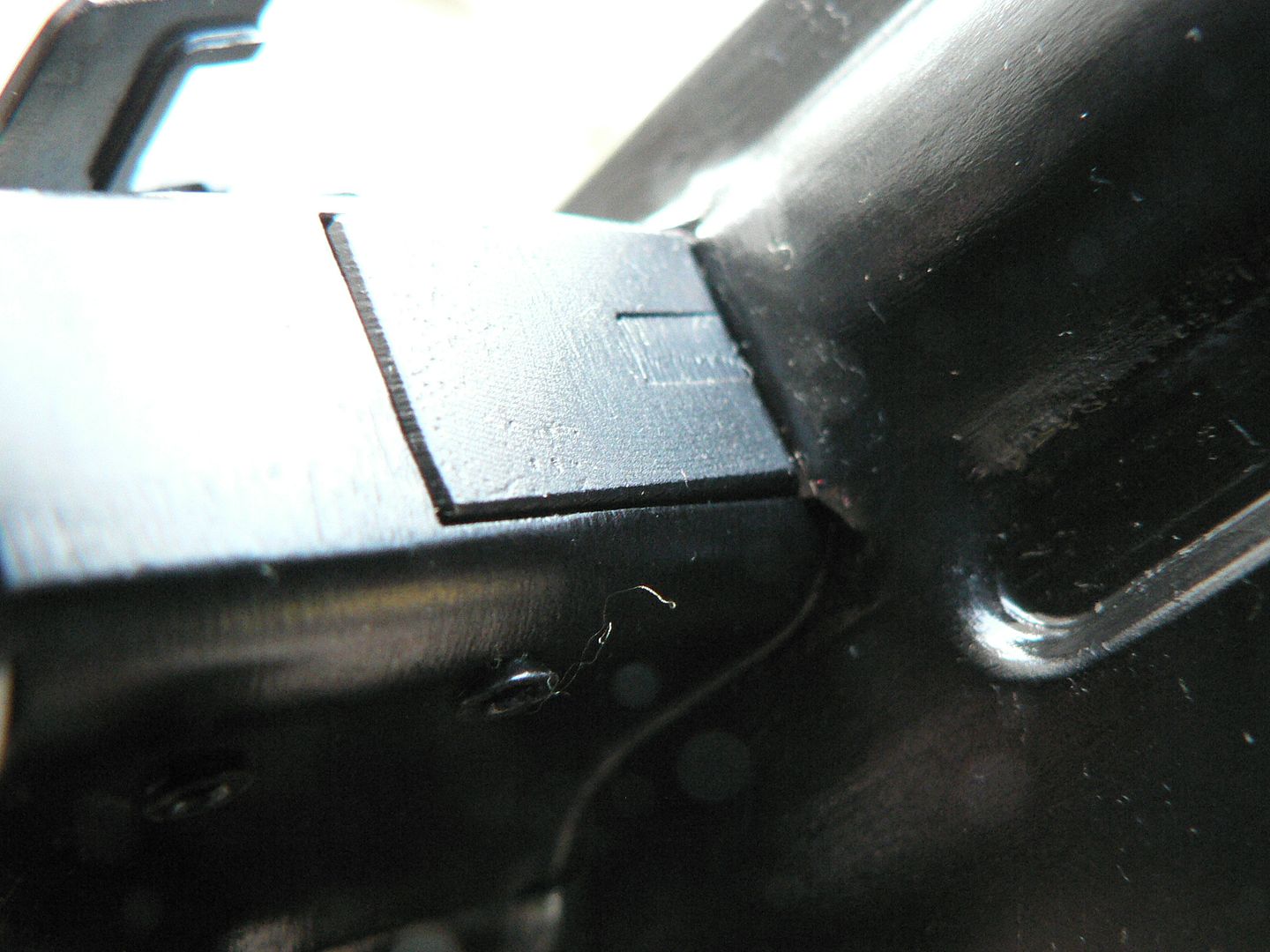 Here, the bolt is forward and the ejector is rotated out of the way: 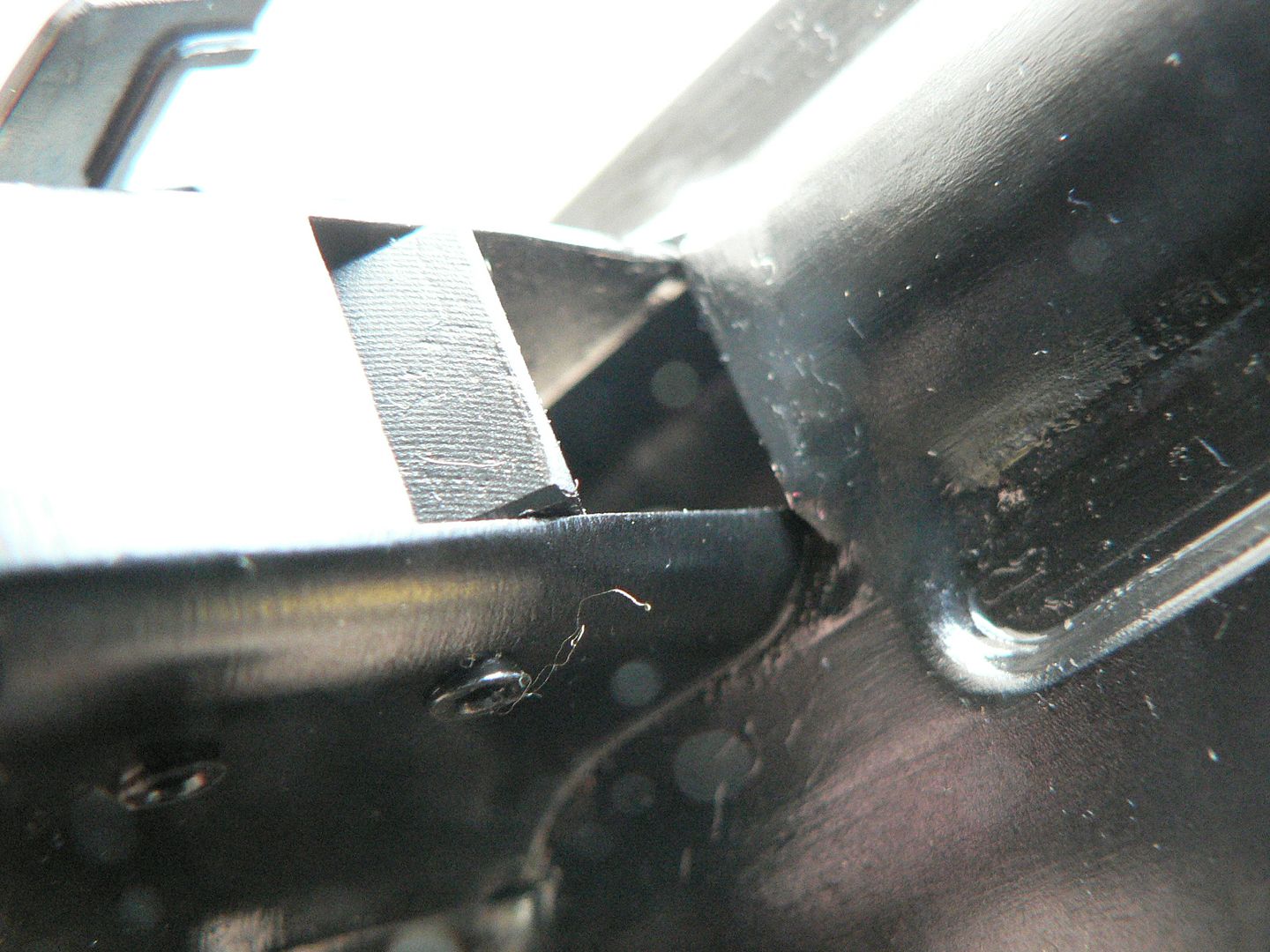 Note: In the above picture, the bolt has been removed and I have swung the ejector further than it would normally go in order illustrate its movement. And back to the first picture again: At the bottom of the picture on the edge of the magazine well is a long pin with a spring coiled around part of it. This pin is the axle for the magazine well upper cover door which is shown closed. There is a lower door too. When the magazine catch (seen poking out of the magazine well in the lower right of the picture) is pressed forward, the coil spring snaps the door open so that a magazine can be inserted. These doors were not present on the first model FG42 and were added to the second model after field tests found that an empty and uncovered magazine well was a great place for dirt to get into the action and render the rifle useless. That's it for the moment. In the next post, we'll move around to the left side of the receiver and get a closer look at the magazine well and it's doors. As always, thanks for your time!
__________________
I promise to be nice and play well with others |
|
|
|
|
09-30-2014, 12:48 AM
|
#11 |
|
User
Join Date: Oct 2007
Location: Maryland
Posts: 340
Thanks: 43
Thanked 107 Times in 51 Posts
|
Here we have the left side of the receiver showing the magazine well with its doors closed:
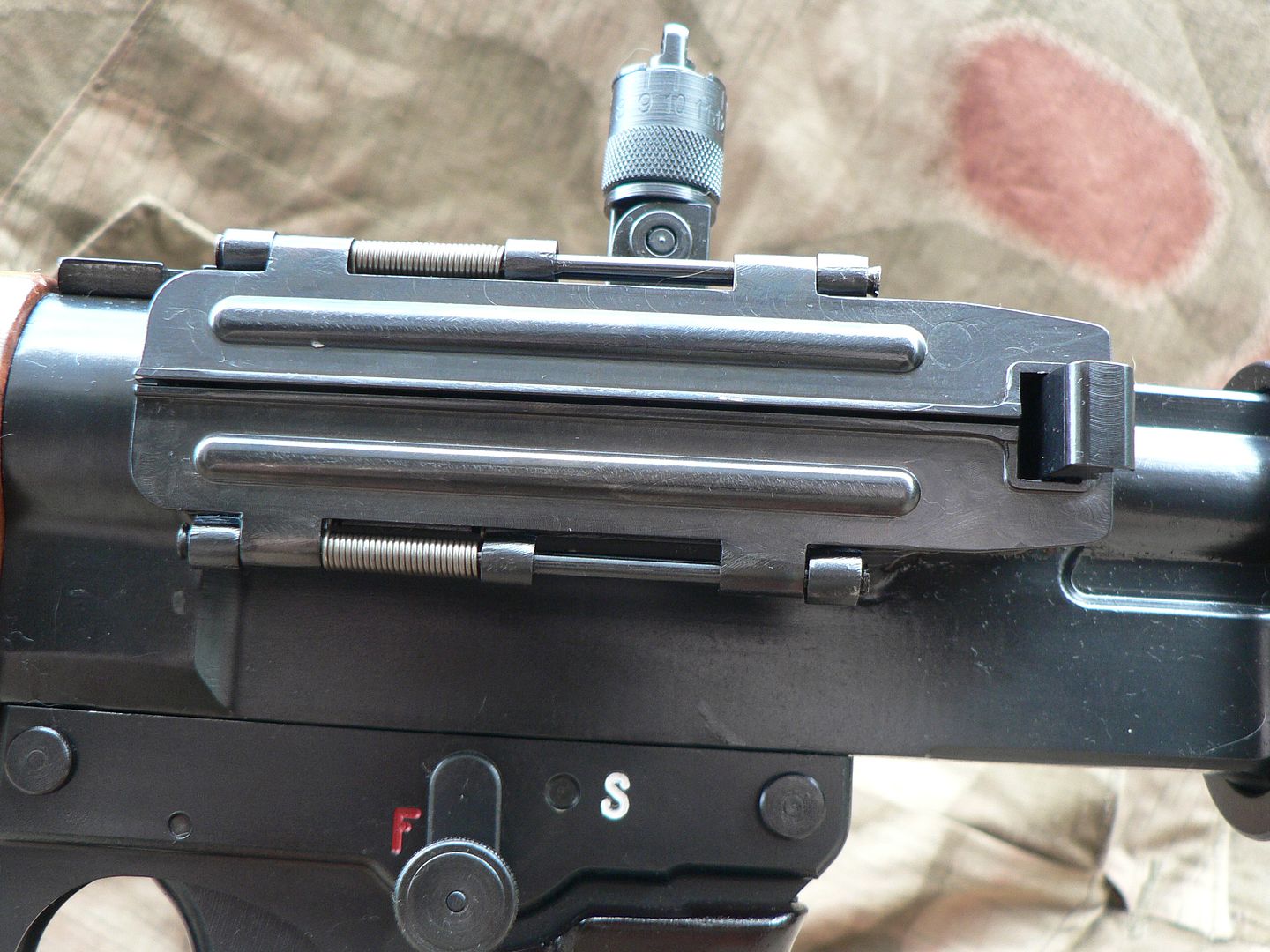 The convex hump running horizontally along each door is a reinforcement rib placed there for rigidity. Since these doors are milled instead of stamped, they are probably not necessary but it looks more authentic. We can see that the long pins they pivot on have been mushroomed at each end to keep them from sliding out of their mounting collars and we can see the coil spring for each door too. Pressing the magazine catch forward enables the doors to snap open and fold themselves back over the magazine well. Inside we can see the bolt: 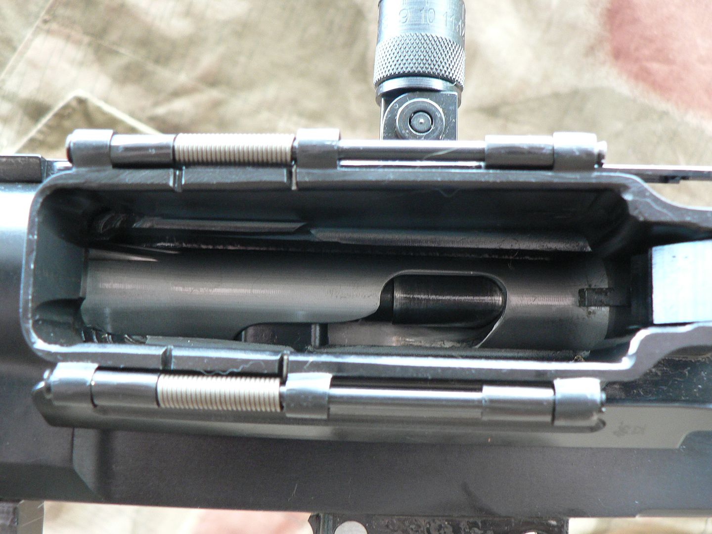 It looks like there's a lot of stuff going on in there!! It's not as much as it looks like though. The curved slot cutout of the silver/grey colored bolt is acted upon by the firing pin yoke (which is part of the bolt carrier) as it cycles back and forth during operation of the rifle. In this way, the yoke acts as a cam, causing the bolt to rotate along its axis thus unlocking and locking the action. At the front lower part of the slot, you can see a blued rectangle. This is the mentioned yoke that holds the firing pin and is part of the bolt carrier. At the upper rear of the slot we can see the firing pin spring guide. Currently, the rifle is not cocked. If it were cocked, the view inside the magazine well would look like this:  Notice that the bolt has not moved at all, neither rearward nor forward and it has not rotated. However, the firing pin yoke (and the entire bolt carrier for that matter because the yoke is just a machined part of the carrier) has moved to the rear a short distance. It is now seen in the middle of the bolt slot. Just behind the rear of the yoke is the rear of the firing pin and part of the firing pin spring guide. It is important to understand that, while this rifle is striker fired, it is not striker fired in the normal sense. The firing pin is securely held by the yoke on the bolt carrier and does not move on its own. Instead, the entire bolt carrier moves forward when the trigger is pulled, taking the firing pin along for the ride and slamming it into the primer on the cartridge case. This is accomplished by using two springs. One of the springs is the recoil spring. It is housed within the bolt carrier itself and cannot be seen until the rifle is disassembled. However, when the bolt carrier is this far forward, the recoil spring doesn't have much forward force left in it. To help out, there is a second spring hidden in the rear of the bolt. This spring is in a highly compressed state when the action is cocked. When the trigger is pulled, the force of these two springs combined is more than enough to set off the primer and ignite the charge. Get it? If not, check out a most excellent video on the FG42 done by Ian McCollum of forgotten weapons. In it, he describes the process better than I can. His video can be seen here with the description of the operation starting at the 5:47 mark: http://www.youtube.com/watch?v=jN4lvZbAe04 But we've gotten off track a little bit. Let's go back and look at the inside of the upper magazine well door opened up and laying against the top of the magazine well: 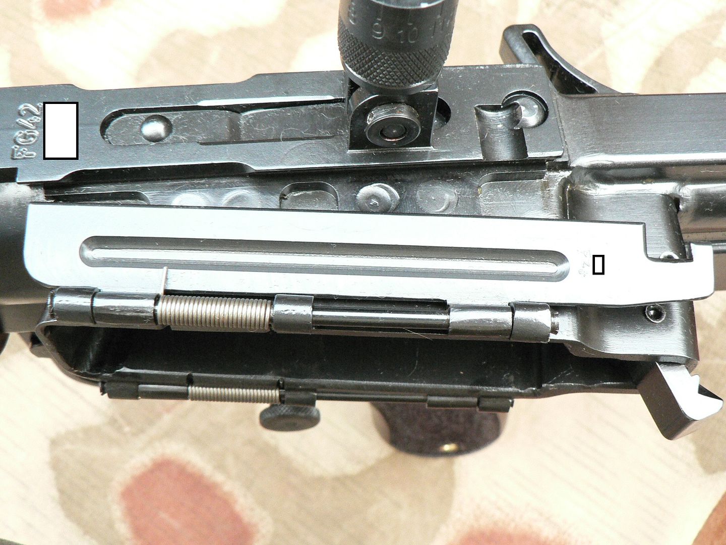 The glare in this picture is on purpose and is intended to showcase the door. Notice that it has a concave area running along its length to simulate the look of the reinforcement rib present on a stamped door. It's another instance of the many intricate details built into these rifles. Here's a close up showing the machining marks: 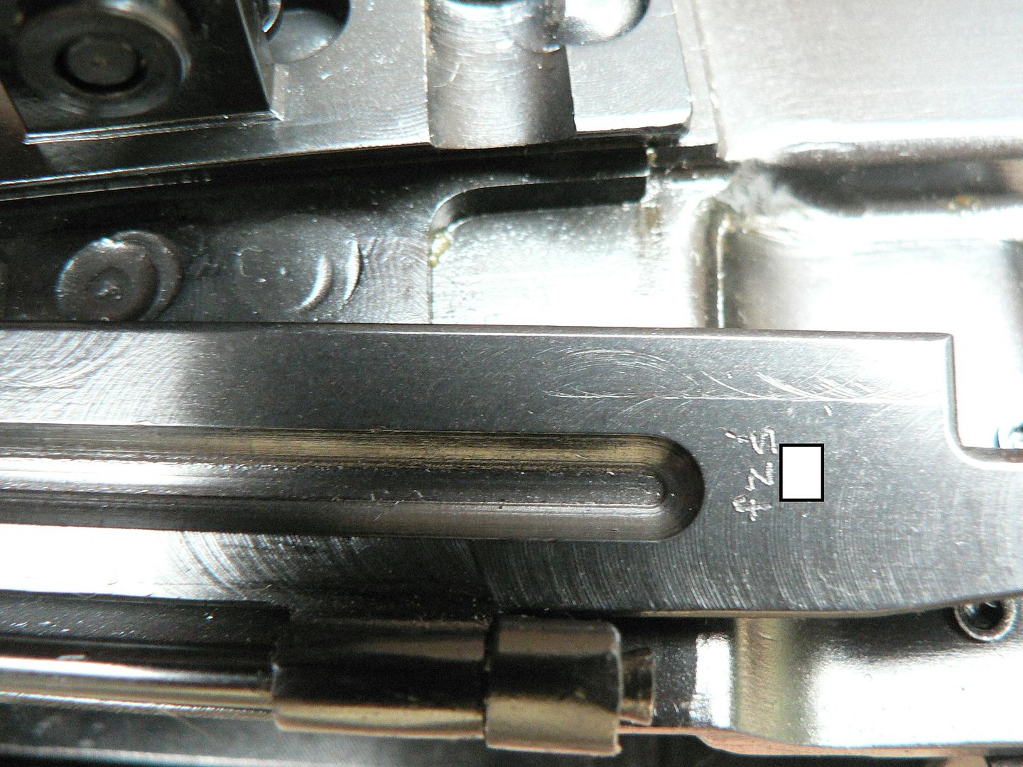 As stated earlier, the "fzs" mark would indicate Krieghoff manufacture and the white rectangle is covering up the serial number. The lower door is marked in a similar way. On to the bottom of the receiver. Here, we have removed the trigger housing assembly and the rifle is not cocked. Forward is to the right: 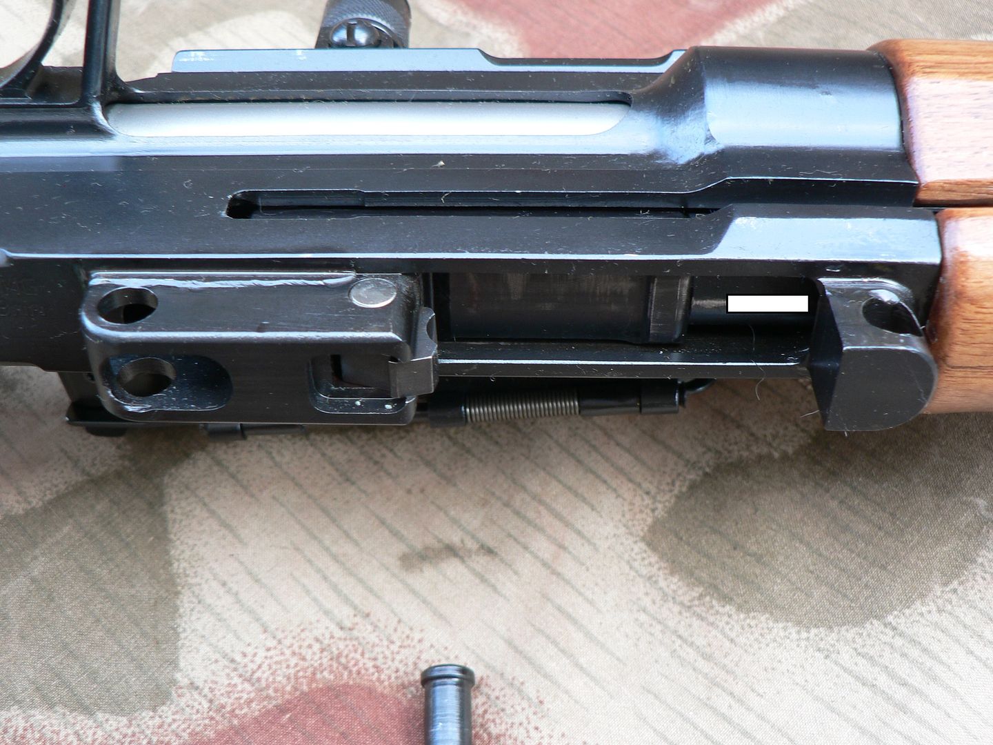 The rifle is laying on its left side and we can see the rear portion of the charging slot running along the right side of the receiver. The coiled spring is for the lower magazine well cover door and is mounted on the magazine well so it has nothing to do with the bottom of the receiver. To the right and just behind the hand guard is the front retaining pin lug for the trigger housing. The rear retaining pin lug is seen to the left of the picture. Moving forward of the rear retaining pin hole, the lug continues some distance until we see a bare metal pin passing through it. This holds the sear (which is seen at the front of the lug) in place. The sear trip in the trigger housing fits up into the square hole machined on the bottom of the lug and engages the catch on the bottom of the sear. As the trigger is pulled, the sear trip moves forward and rotates the sear counter-clockwise against spring tension when viewed from the right side of the rifle, pulling a catch machined on its upper surface (not seen) from engagement with a notch on the bottom of the bolt carrier allowing the carrier to run home and fire the round. The slot on the bottom of the bolt carrier can just barely be seen above the sear at the very front of the retaining pin lug. The white rectangle is covering up the serial number on the operating rod. Here is a shot showing the action cocked: 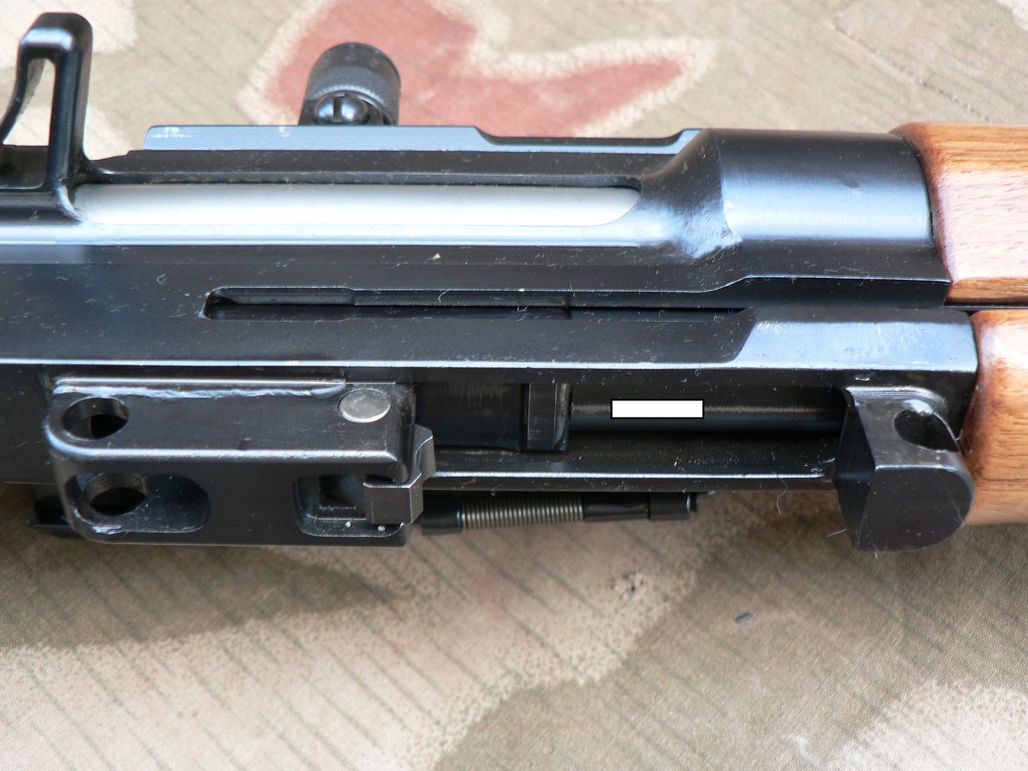 Notice that the bolt carrier has moved to the rear and the cocking notch on the bottom of it can no longer be seen. It is currently engaged by the catch on top of the sear. Behind the white rectangle covering the serial number is a blued rectangle running crossways in the receiver slot. This is where the bolt carrier ends and the operating rod begins. Here's a close-up of the sear area which better shows the cocking notch cut into the bottom of the bolt carrier: 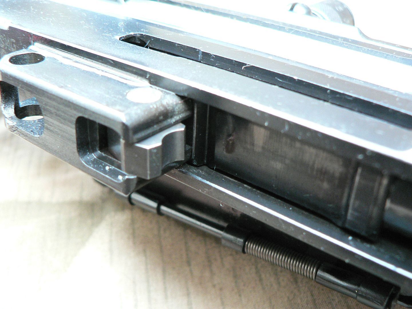 The dished out area on the front of the sear is where the disconnector lug fits. This receiver mounted sear arrangement is not present on original rifles and is part of the design modifications done to the ignition system in order to make it a purely semiautomatic only firearm. On original rifles, the fire control group is completely different in design and all parts are mounted within the trigger housing assembly. So how does the feel of the trigger pull on the SMG rifle differ from the German made FG42? I don't know at present but I will very soon because I'll be comparing my FG42 to an original bring back rifle. I will be taking notes and pictures which will be reported so be looking for that in the not too distant future. The only other thing of note on the bottom of the receiver is the Smith Manufacturing Group mark. It is placed on a flat area just behind the trigger housing and forward of the stock: 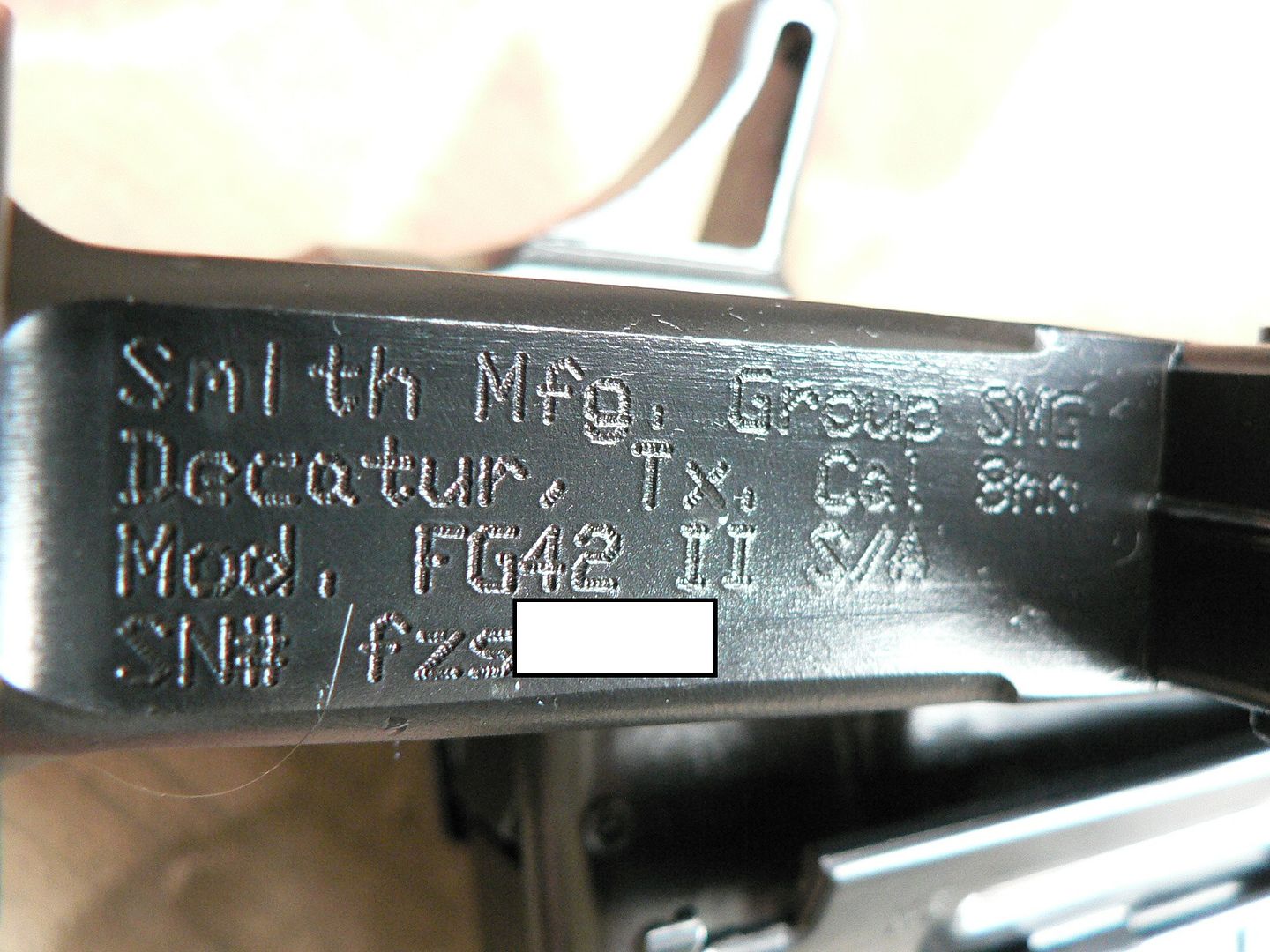 It appears to be electro-penciled. Not much to say here as it should be pretty self explanatory. As usual, the white rectangle is where the serial number is marked. It's nice that SMG placed it here on the bottom in a discreet area instead of emblazoning it along the side as some morons would most assuredly do........you know who you are! We're done for tonight but I'll be back at it soon.
__________________
I promise to be nice and play well with others Last edited by Wilhelm; 09-30-2014 at 10:31 PM. |
|
|
|
|
10-01-2014, 12:18 AM
|
#12 |
|
User
Join Date: Oct 2007
Location: Maryland
Posts: 340
Thanks: 43
Thanked 107 Times in 51 Posts
|
Tonight, we are only going to look at the stock and the rear of the receiver so it's going to be a short post.
The laminated stock is made from 27 (if I counted correctly) layers of walnut. Where SMG found a lumber producer that was willing to produce walnut blocks that thick and with that many layers is beyond me but it is a thing of beauty. It has very little drop to it as you move to the rear and, even when it does drop, it rises again where it meets the shoulder. This straight line configuration, combined with the excellent muzzle brake and the buffer (discussed later), keeps muzzle rise at an absolute minimum. The entire stock is hollow because it slides over the rear of the receiver. It is available in both a dark and a light finish. Both are shown below: 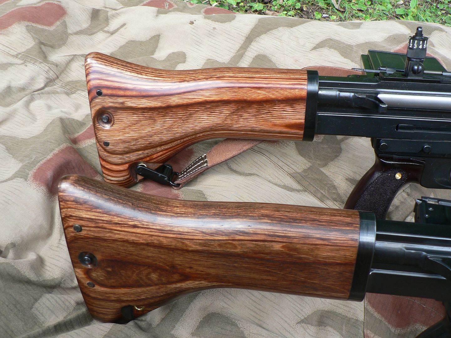 The steel butt plate commonly found on German rifles is absent on the FG42. Instead, there is another block of wood inserted and into the back of the hollow stock and held in place with two pins. This insert forms the rear of the stock and it has finely cut ribs for grip when the rifle is shouldered: 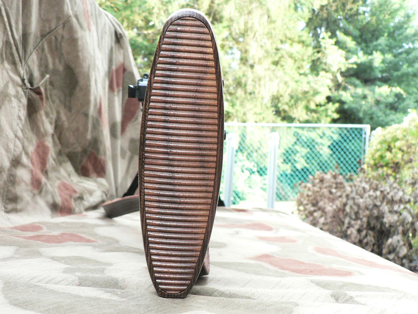 On original rifles, the union of this insert and the hollow stock was a weak point. With use, the pins holding the insert in place would crack out the end of the stock and essentially render it useless. The rifle can still be fired without the stock in place but it cannot be shouldered. Let's look at those pins and discuss what SMG has done to address the problem: 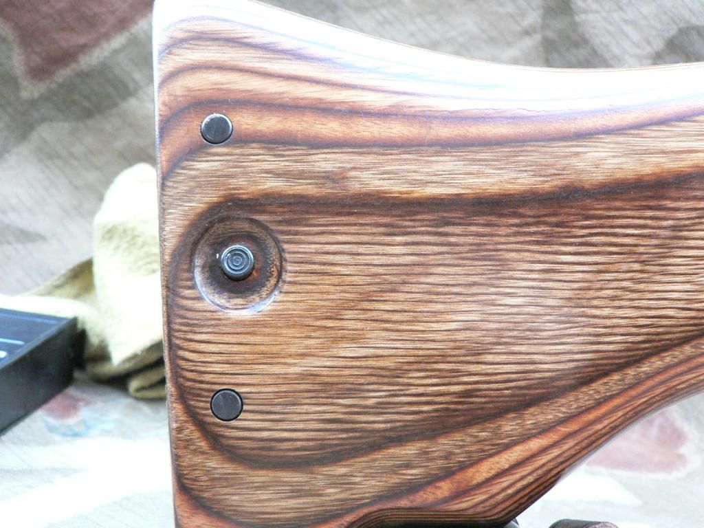 SMG has done two things to mitigate the "pin pullout" problem. 1. The pins have been moved farther apart. This makes the insert more stable in the stock, spreading impact forces over a greater area. 2. Aluminum reinforcement tabs are hidden inside the stock so that the pins are pulling on metal and wood instead of just wood. According the SMG, this eliminates the problem. Time will tell but their solution seems reasonable. Between the two pins is a little button with concentric rings machined into it. This is the push button for stock removal. Simply press the button and slide the stock to the rear off the receiver. In this picture, the stock has been removed and placed below the receiver in a position relative to it being mounted: 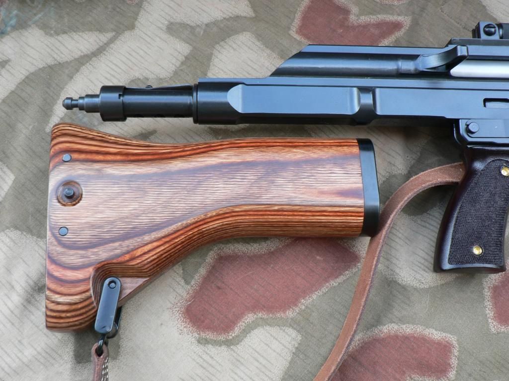 Sticking out the rear of the receiver is the buffer. We'll take a closer look at the buffer later but for now, all you need to know about it is that it has a heavy spring inside and serves three purposes. First, it lessens the felt recoil of the rifle. Second, it serves as the mechanism that holds all of the guts in the receiver where they belong. Third, it is the attachment point for the stock. You see, the stock does not attach to the receiver; it merely rides over the receiver. Do you see that little grooved and pointed nub sticking out the extreme rear of the buffer? That's the only thing holding the stock in place. The push button on the side of the stock pushes in on a spring loaded collar inside the stock. This collar engages the groove on the nub and this holds the stock on the rifle. The nub is conical on the tip so that you don't have to press the button to mount the stock; just slide it over the rear of the receiver and push. It sounds like it would be fragile but it seems to work just fine. The reason the stock slides over the receiver instead of attaching to it is because the entire rifle actually recoils into the stock. Again, we'll discuss that in detail later when we look at the buffer. Notice that the sling is mounted to the stock with a funky metal thingee. We'll talk about that later too when we look at the sling. At the front of the stock is a blued steel ring: 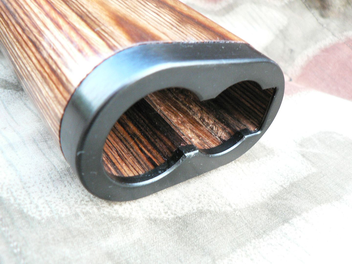 On original rifles, this part would be stamped but here it's milled just like everything else. This ring protects and strengthens the front opening in the stock. Notice that it is cut out in roughly the shape of a receiver cross section. This helps to keep it from rattling around too much on the receiver. Let's go back to the picture showing the stock below the receiver: Notice that there is a bulge in the receiver just above the front ring on the stock and another at the rear of the receiver where the buffer is mounted. These, and the flat area on top of the receiver, are the main surfaces that the stock rides against. This arrangement minimizes contact points between the receiver and stock while keeping the two assemblies running parallel to each other at all times. Without them, the stock would flop around quite a bit. That's it for the stock. Short (kinda') and sweet for once. See you soon!
__________________
I promise to be nice and play well with others |
|
|
|
|
10-03-2014, 01:46 PM
|
#13 |
|
User
Join Date: Oct 2007
Location: Maryland
Posts: 340
Thanks: 43
Thanked 107 Times in 51 Posts
|
Alrighty then. It's time to start taking this thing apart. Actually, we already began by taking the stock off. The next thing that comes off is the buffer so let's take a look at that.
Here, we are looking down at the rear section of the receiver with the buffer still in place: 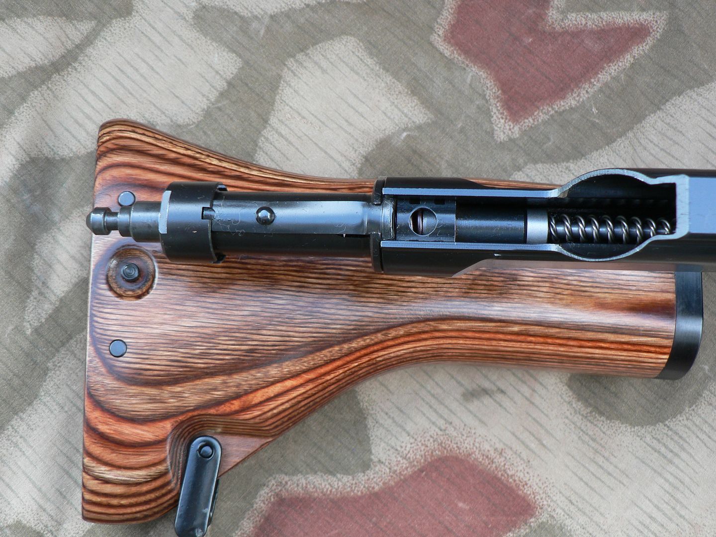 It all looks complicated and I'm sure that manufacturing it all WAS complicated. However, the way it all works is very simple. The buffer itself is nothing more than a tube with a heavy spring inside and a plunger sticking out each end. The plunger facing inside the receiver fits over the end of the stainless steel recoil spring guide. The spring guide is the silver/gray rod disappearing into the receiver with a coiled spring wrapped around it . That spring is the recoil spring. As the rifle fires and the bolt group begins to move to the rear, the recoil spring becomes increasingly compressed. As the recoil spring compresses, rearward inertia is transferred to the recoil spring guide and it tries to move to the rear as well. In doing so, it presses on the plunger sticking out the end of the buffer. The plunger then starts to compress the VERY heavy buffer spring. As it compresses, reward force is imparted on the plunger sticking out the back of the buffer, into the stock and then into your shoulder. While these things are going on, the entire rifle is moving to the rear independent of the bolt group and this force is transmitted to, and this is important, the buffer body, NOT the stock. Remember that the stock is mounted to the buffer ONLY. Thus, the entire rifle begins to move rearward into the stock and this force is again transferred into the buffer spring through the buffer body. What we're getting at here is that ALL recoil force passes through the buffer spring first before being transferred to the stock and, ultimately, your shoulder. The end result VERY little felt recoil. It's somewhere between an AR and an AK in my estimation. This design is pure genius and is by far the most pleasant experience I've ever had with any rifle firing a full sized round. Now that we know how it works, let's remove it. About halfway towards the rear of the buffer is a little round bump on top. This is a rivet that holds a curved leaf spring in place on the buffer body. At the front, this spring rises into the notch cut into the receiver keeping the buffer from turning. Use your thumb to press down on the spring and then turn the buffer 90 degrees in either direction as shown here (we turned it clockwise as seen from the rear): 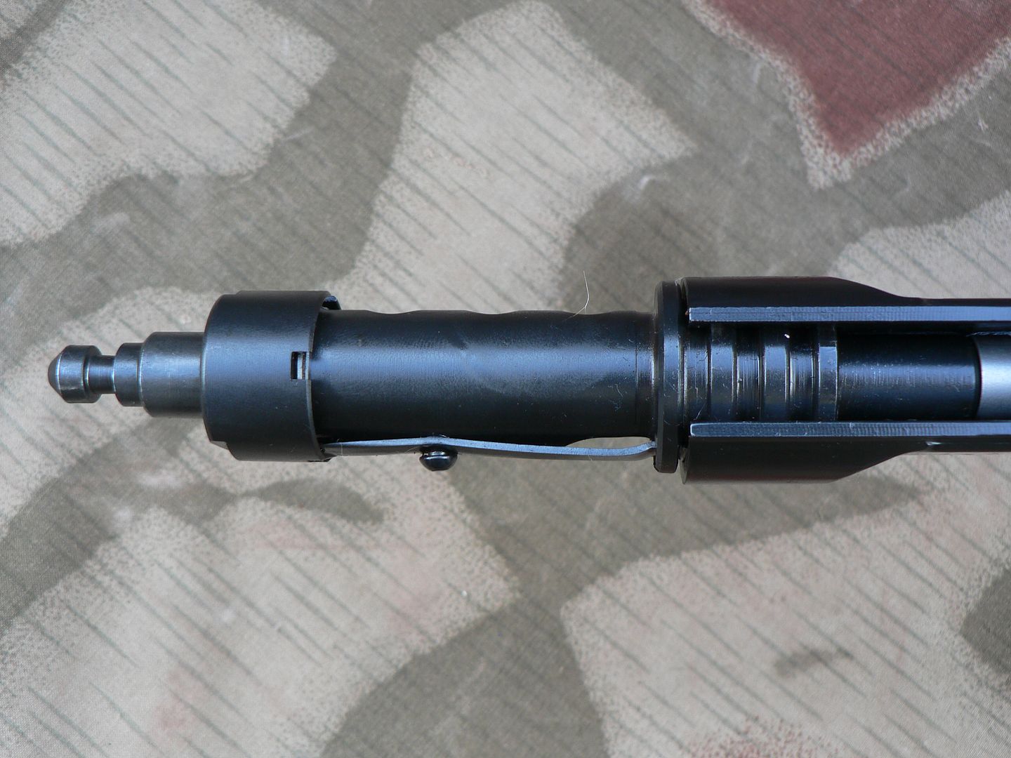 This disengages three interrupted rings machined into the buffer body from three grooves machined into the rear of the receiver. Now pull the buffer to the rear and out of the receiver. You may have to wiggle it just a little as you pull because it is a very closely fitted part. Here's what the grooves in the back of the receiver look like: 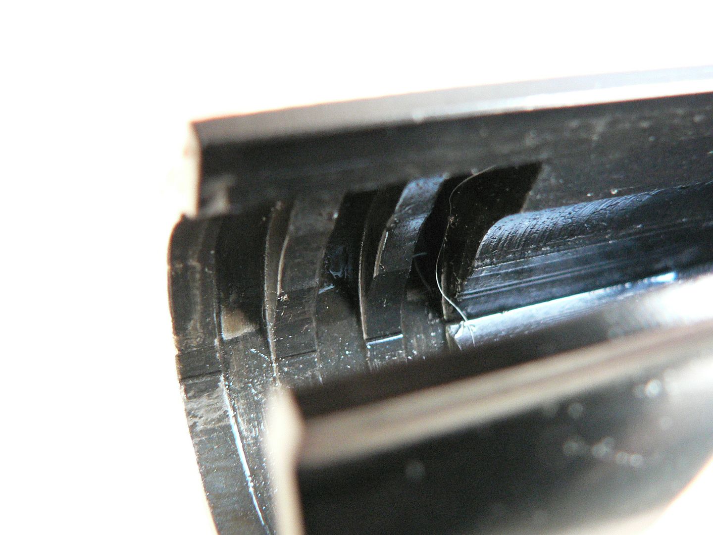 Here is the buffer removed from the rifle: 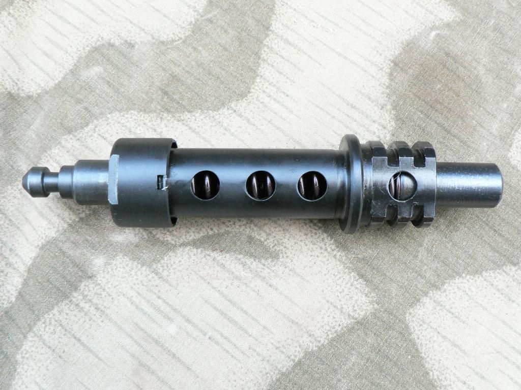 I have turned it upside down because we have already seen the top and the side of it. Forward is to the right of the picture. Sticking out the front is the plunger that fits over the recoil spring guide. Next are the three interrupted rings that secure it in the receiver. Through the forward hole, we can see where the buffer spring meets the front plunger. Passing to the rear, we come top another ring that is uninterrupted. This rests against the back of the receiver and stabilizes the buffer so that is won't wiggle and destroy the mounting rings and/or their grooves in the receiver. We then have three more holes bored through the buffer body. I assume that all four of the holes are there for a number of reasons; some these being to relieve pneumatic pressure as the buffer does it's thing, allowing water and debris a way out (and in for that matter), and allow lubricating of the buffer spring. There may be other reasons that I am too dim to recognize too. Next up is the buffer cap. It is threaded over the rear of the buffer body and holds it all together. Notice that it has a small notch cut out of it. There is another one 180 degrees around the circumference of the cap and either one can be engaged by the rear of the leaf spring riveted on the top of the body to keep the cap from unthreading itself during use. There are also two flat areas machined into the cap so that a wrench can be used to unthread the cap if it's stiff. Sticking out the back of the buffer is the rear plunger which we have already talked about. I'd like to take the buffer apart but I don't think it would be prudent. The spring is so heavy that I can't even budge it unless it's installed in the receiver and I'm pushing on the rifle. To move it by hand when it's off the rifle is impossible for me. I have no idea how long that spring is when not compressed and I'm afraid that I might not get it back together again without mangling the entire assembly so we're just gonna' leave that thing alone. Next, pull out the recoil spring guide and the recoil spring. We'll see those two parts in their entirety in a little bit but for now I want to direct your attention to the rear of the spring guide for just a moment: 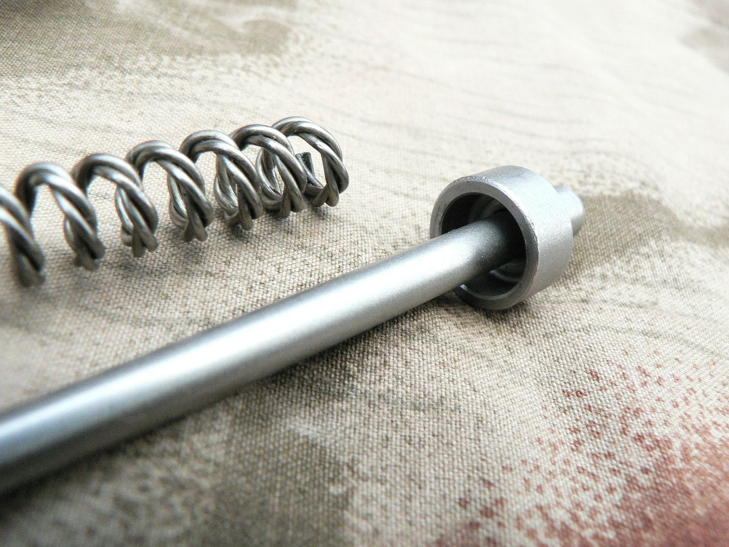 Here, we're looking at a cup machined into the guide for the spring. It's just another example of the attention to detail present in this rifle. Most folks wouldn't even give it a second thought but I notice little things like this. I'm sure a flat ring on the rod would work just fine but the cup.....well, that reminds me of something the Swiss would do. Very nice! Also notice the three stranded recoil spring. This was done on original rifles to combat spring fatigue and has been carried over into the SMG rifle as well. Continuing on, pull the charging handle fully to the rear as shown here: 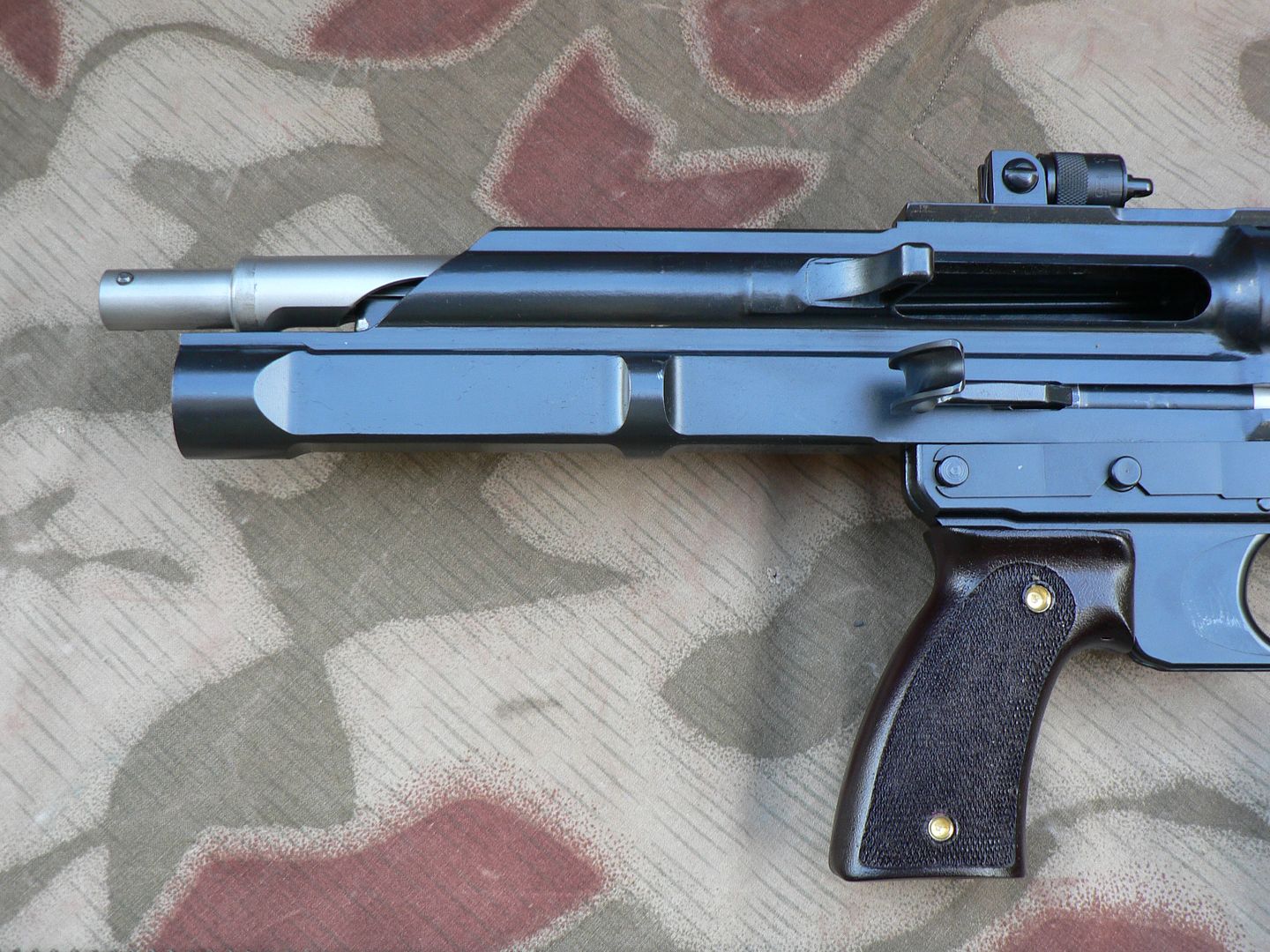 It will require more force than you would expect because remember that we have another spring hidden in the bolt that must be compressed as the action is drawn to the rear. Notice that the rear of the bolt is now sticking out the back of the receiver. Pull the charging handle out of the operating rod and set it aside: 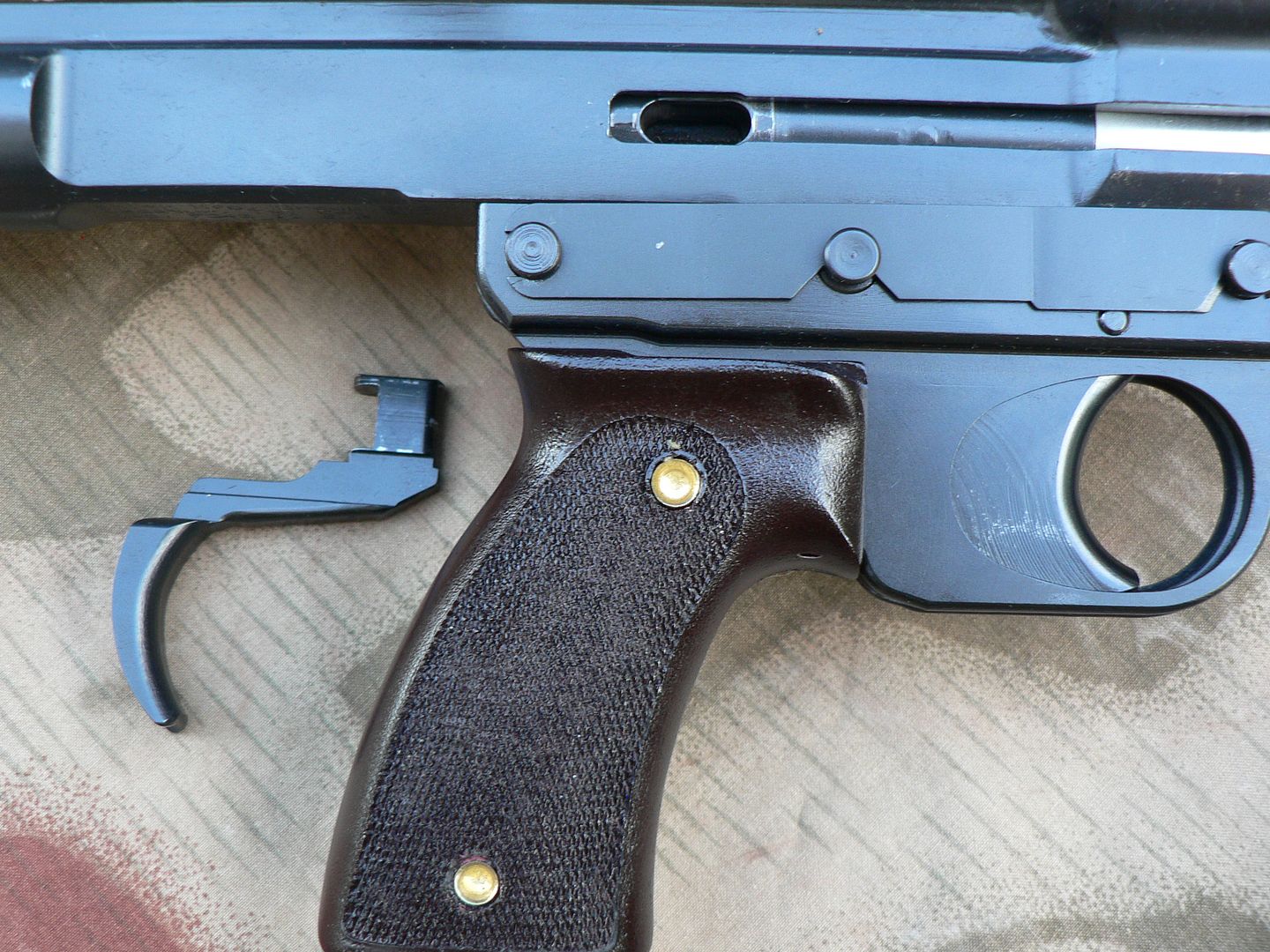 There is a little captive plunger inside the operating rod that is pushed forward by the recoil spring. If this plunger is in the forward position, the charging handle cannot be removed. In this case, just point the rifle upwards and tap on the back of the bolt assembly or rear of the receiver and the plunger will move backwards releasing the charging handle. Here's a close-up of the charging handle: 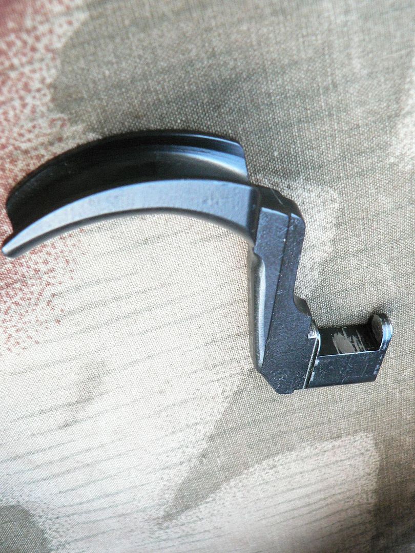 Notice the notch that the plunger fits into. The bluing has been removed where the two parts contact each other. Were it not for this plunger and notch arrangement, the charging handle would eventually fall out in use because it reciprocates with the bolt group. In the next post, we'll remove the bolt group and take a look at it before starting to disassemble it into it's various components. Ok bye!
__________________
I promise to be nice and play well with others |
|
|
|
|
10-05-2014, 01:12 PM
|
#14 |
|
User
Join Date: Oct 2007
Location: Maryland
Posts: 340
Thanks: 43
Thanked 107 Times in 51 Posts
|
Picking up where we left off, pull the bolt group out of the receiver. As you remove it, be aware that the spring in the bolt is compressed and trying to push the bolt to the rear. If you are not actively squeezing the bolt and carrier, the bolt may snap rearward with some force, banging the front of the cam slot into the front of the firing pin yoke. I'm sure that this cannot be good for the components. Here is what the right side of the assembly looks like when as it comes out of the rifle:
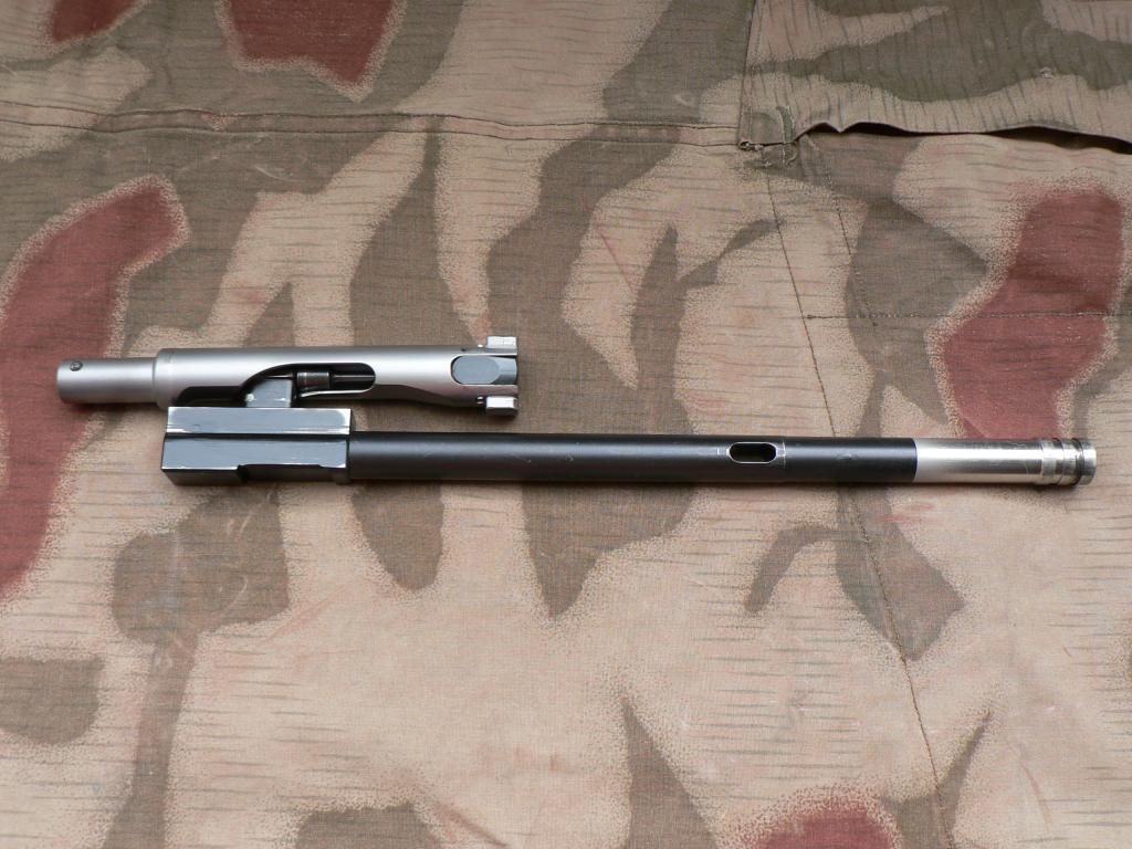 The two locking lugs on the bolt are facing up and down. This is the unlocked position, allowing the bolt group to reciprocate inside the receiver. Between the locking lugs is the extractor. The firing pin can be seen in the cam slot too. Part way up the operating rod is the cutout where the charging handle fits with the stainless steel gas piston in front of it farther up the rod. We'll take a closer look at all of the individual parts in a little while. Here's the left side: 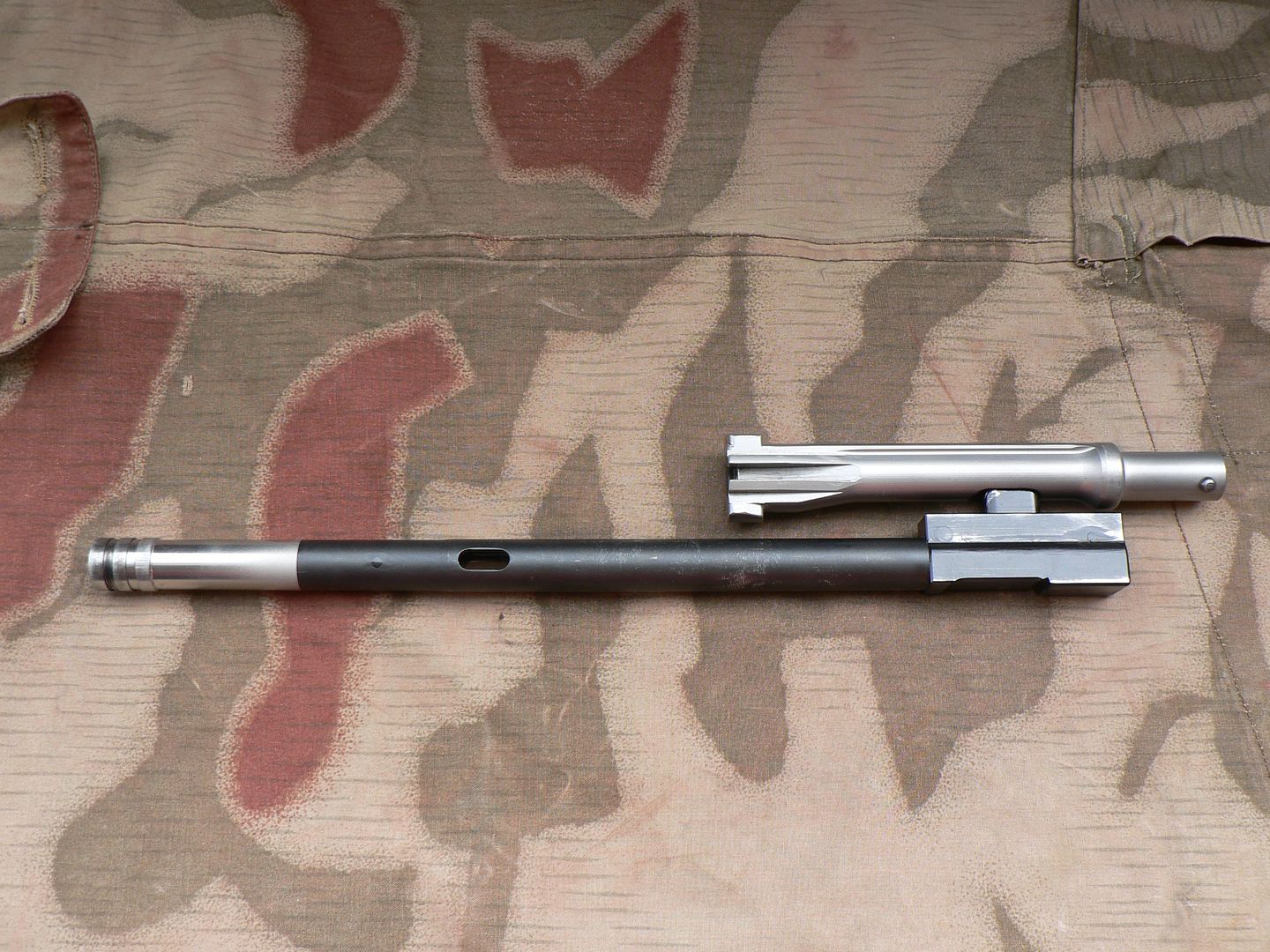 The little round nub at the rear of the bolt is the pin that holds the firing spring and all of it's hardware in place. At the front of the bolt is the ejector slot. Now carefully release tension on the internal spring by rotating the bolt and easing it to the rear until it stops. It will now look like this: 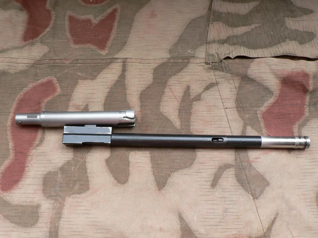 The bolt has rotated 90 degrees and the locking lugs are now sticking out to the sides. If the assembly were in the rifle, they would be engaging the cutouts in the trunnion and the action would be locked. Up in the charging handle slot, you can see the plunger that holds the charging handle in place. This has nothing to do with the bolt position. It just slides back and forth with out the recoil spring in place and happened to be slid forward when the picture was taken so ignore that for now. The gray rectangle on the rear of the bolt is covering the serial number. And a shot of the left side after the bolt has been eased to the rear.: 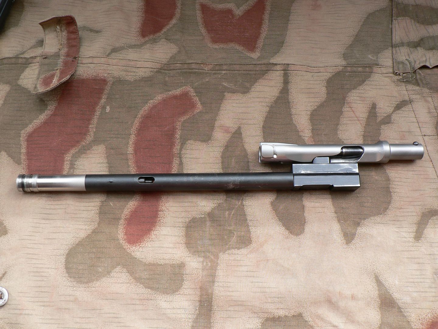 The extractor is on the bottom and the ejector slot is facing up. Next is removal of the firing spring. I hesitate to call it the firing pin spring because it really has nothing to do with the firing pin. This spring is necessary to keep tension between the bolt and the bolt carrier; the rifle wouldn't work without it. It is also necessary when the trigger is pulled to force the carrier home with enough force to reliably set off the primer. So, instead of calling it a "firing pin spring", I tend to call it a "firing spring" as I feel that's a more appropriate name for it. Whatever name you decide to assign this spring, to remove it for further bolt group disassembly, we must first remove the pin that holds it in place. To do so, refer to the picture below: 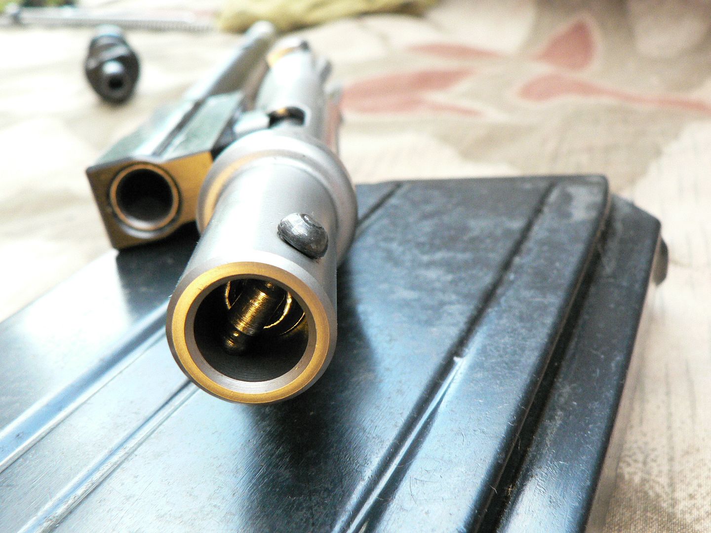 The above picture is a close-up of the rear of the bolt. Notice that there are a couple grooves in the retaining pin. These are indexed by the edge of a hole bored into the conical spring plunger. This plunger is under pressure from the firing spring at all times, even when the bolt is fully to the rear, so the retaining pin is held in place securely. To remove the pin, the plunger must be pressed forward into the bolt and the pin can then be pressed out. This sounds simple enough but it's actually quite fidgety and, honestly, it's a big pain in the behind to mess with. The problem is that the plunger wants to rock in the bolt when you try to depress it and is ends up getting stuck in place. If the plunger were made thicker length wise, I think the problem would be eliminated. Trying to get this thing depressed straight down into the bolt is like trying to mess around with a commercial rifle that you need special tools and knowledge to disassemble. It's insanely frustrating to say the least. Is my opinion pretty clear on that? I think the original design used some sort of cup that fit into the hole and rotated to lock and it was held by spring tension too. Whatever the design, is was prone to failure so SMG came up with the pin and plunger idea as a replacement. Again, I think it would be fine if they simply made the plunger deeper so that it couldn't rock in the hole. Anyway, fidget the plunger down and pull the pin out. Now play around with the plunger for a few minutes (I'm not exaggerating here) until you get it unstuck in the bolt and pull it out. The firing spring will come out with it. There is also a spring guide that should come out. If it does not, just tip the bolt back and it will slide out. Here's what it looks like disassembled: 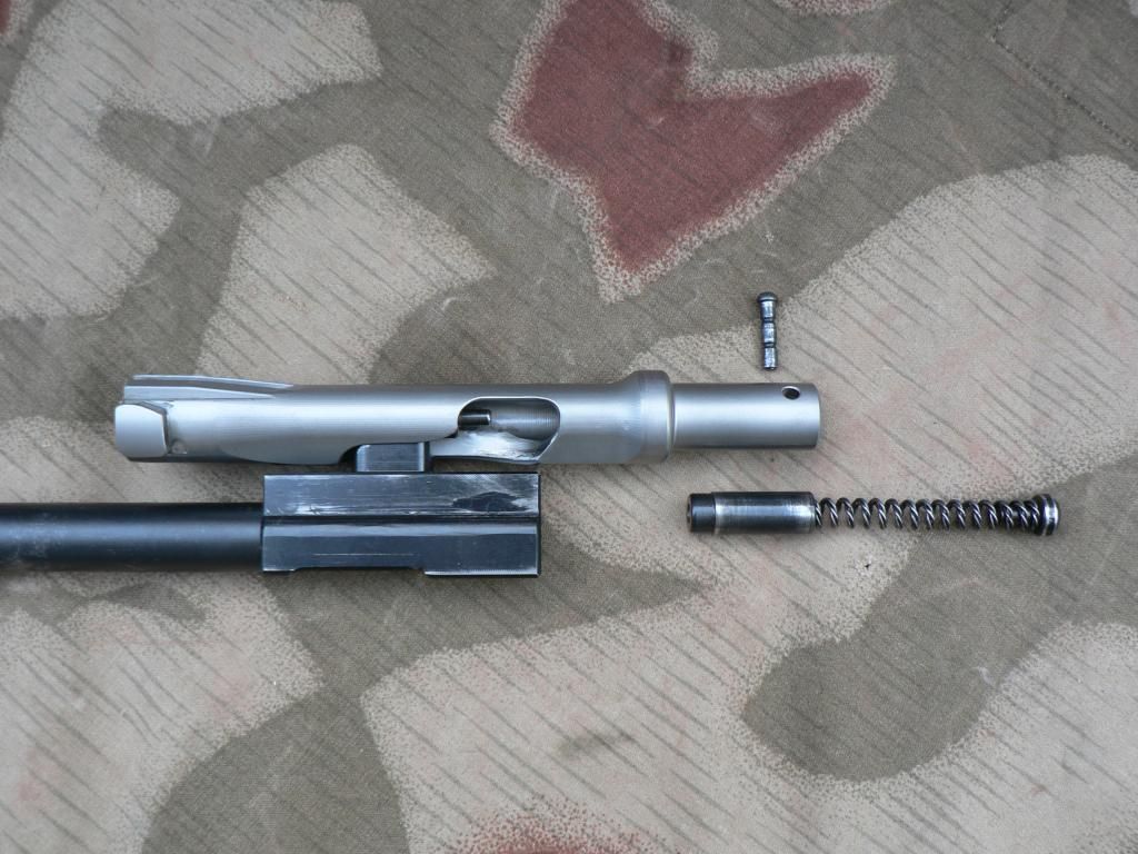 Let's take a look at the individual parts. Here's the retaining spring and plunger: 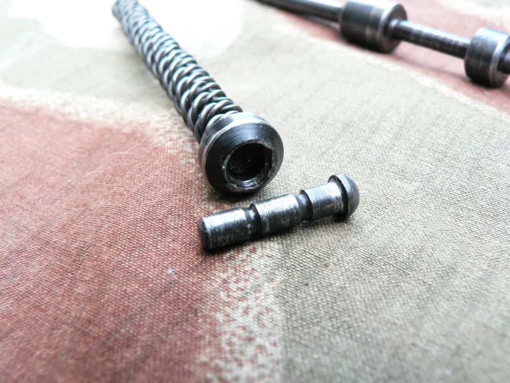 Now we clearly see the grooves in the retaining pin, the conical plunger and we can see how they fit together to lock the retaining pin in place. You can also see the wound firing spring. The spring has a slightly smaller inside diameter than the outside diameter of the stem sticking out the front of the plunger so the two parts stay together as a unit. Here's the rear of the firing spring guide showing the hole that the spring fits into: 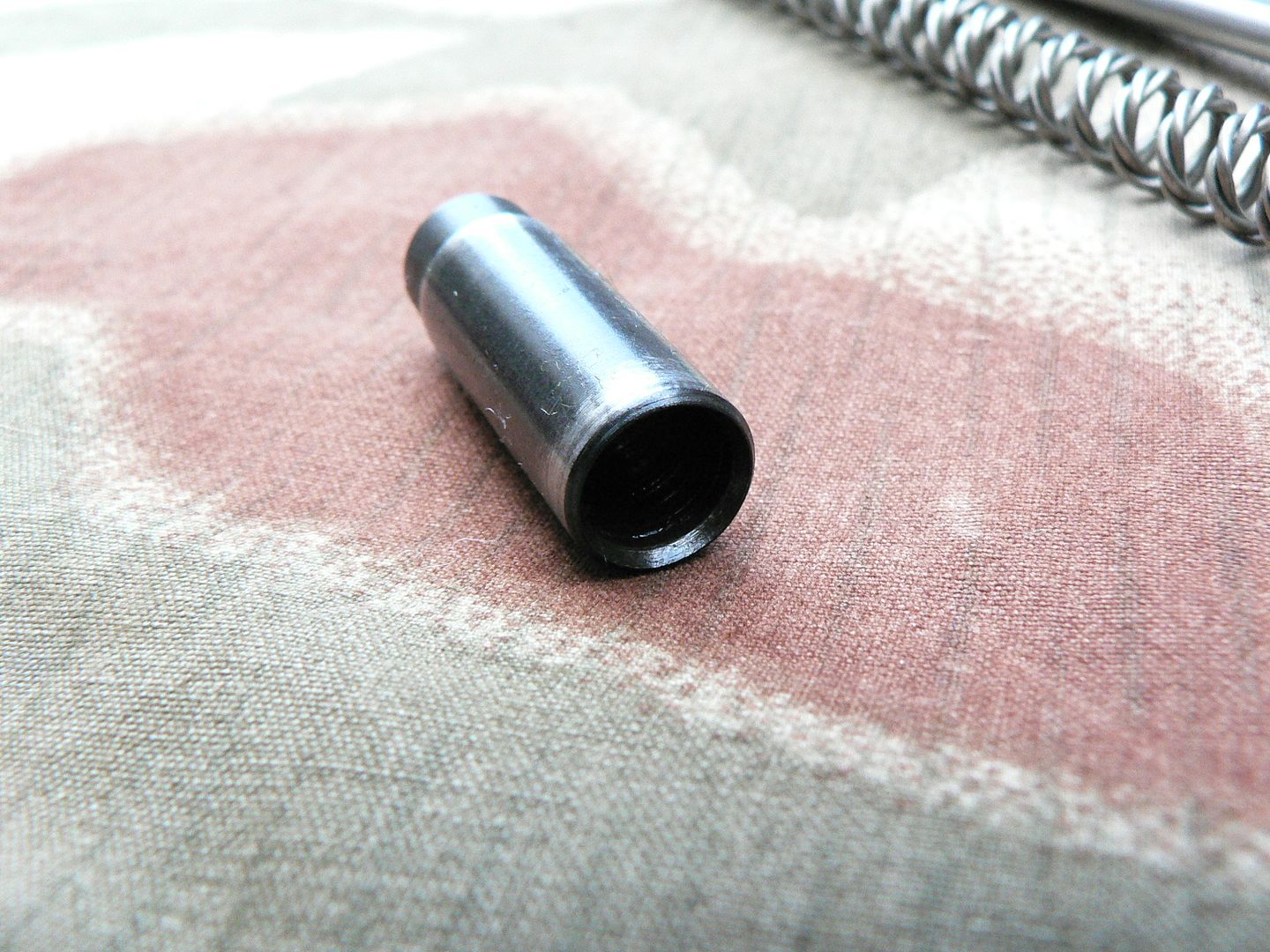 And here's the front of the firing spring guide showing the hole that fits over the stem on the back of the firing pin: 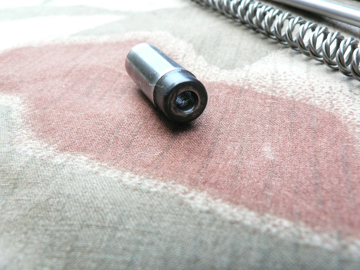 To separate the bolt from the bolt carrier, simply push the bolt forward while pulling up and away form the carrier: 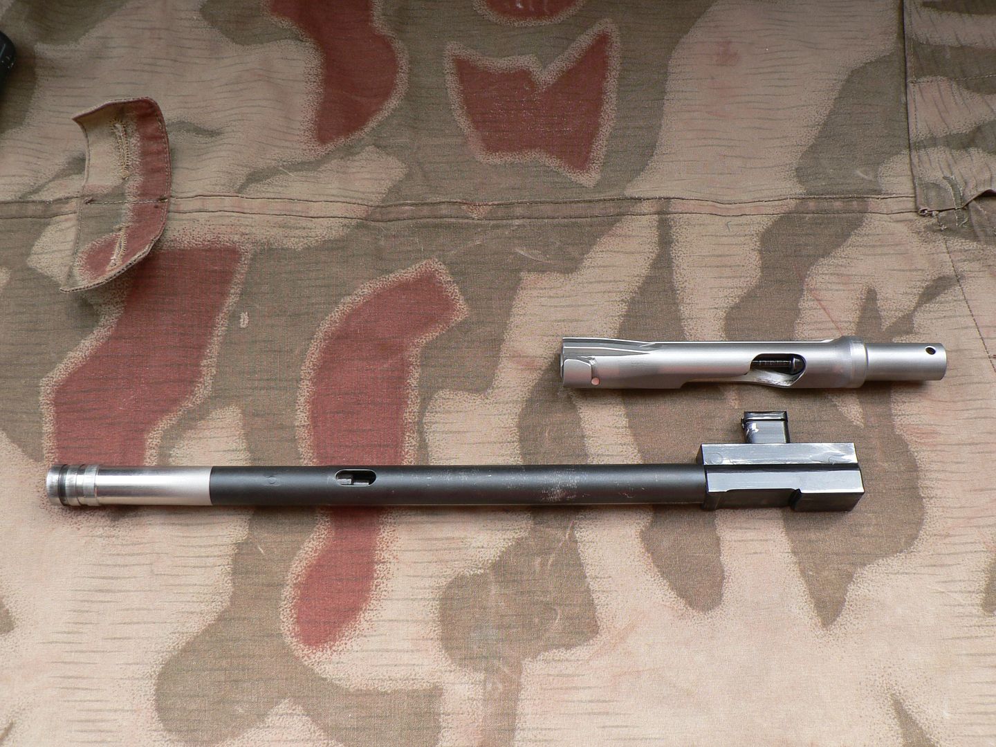 Now tip the bolt up and the firing pin will just fall out the back. Here's the firing pin: 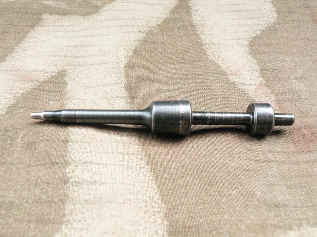 For those that have never seen a firing pin before, the front is to the left. The stem sticking out the back fits into the hole on the firing spring guide and the skinny part in between the two collars is where it fits into the yoke on the carrier. Here's a picture showing it fitted to the carrier: 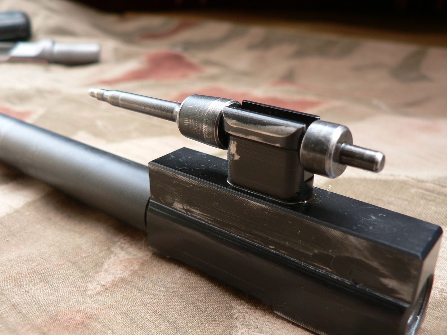 And here's a top view of that as well: 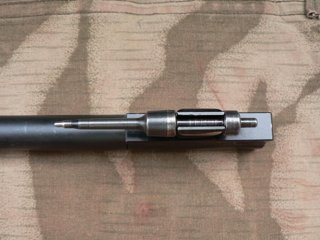 I want to again note that the firing pin DOES NOT move independently as it does on most rifles. It is held fast by the bolt carrier. When the trigger is pulled, the entire carrier moves forward under spring pressure carrying the firing pin along with it to fire the round. So, this rifle is striker fired, not hammer fired. I assume that's clear by now but I just want to make sure that you fully understand. Now let's take a closer look at the bolt. Here's the bolt face: 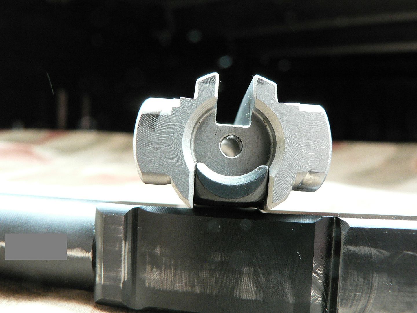 It's resting on the bolt carrier so ignore that. At the top of the picture is the ejector slot and the locking lugs are sticking out to the left and right. Look carefully at the top of the left lug and the bottom of the right lug and you will see wear marks where the lugs strike and ride in the trunnion locking grooves. This is normal wear. When this picture was taken, I had put 80 rounds through the rifle and SMG had put an unknown number through it during test fire and sighting in. If your bolt does not look like this, it means that you are not shooting your rifle......do so immediately. Another shot of the bolt face in slightly different light for wear mark comparison: 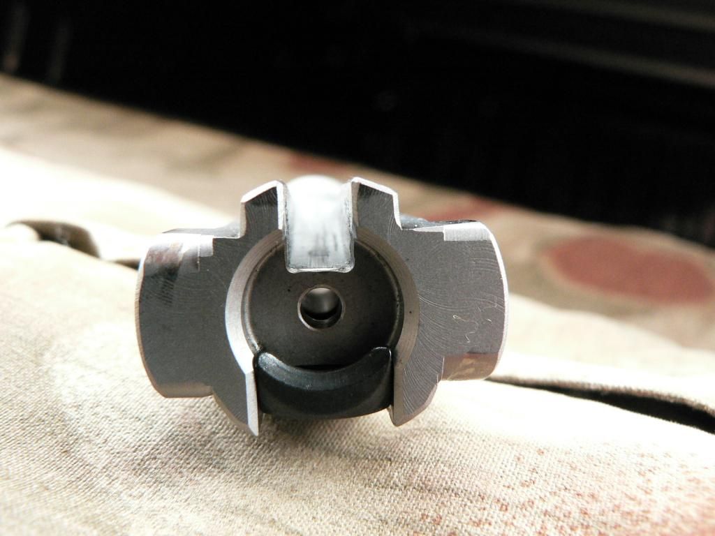 Here's a detail shot of the ejector slot: 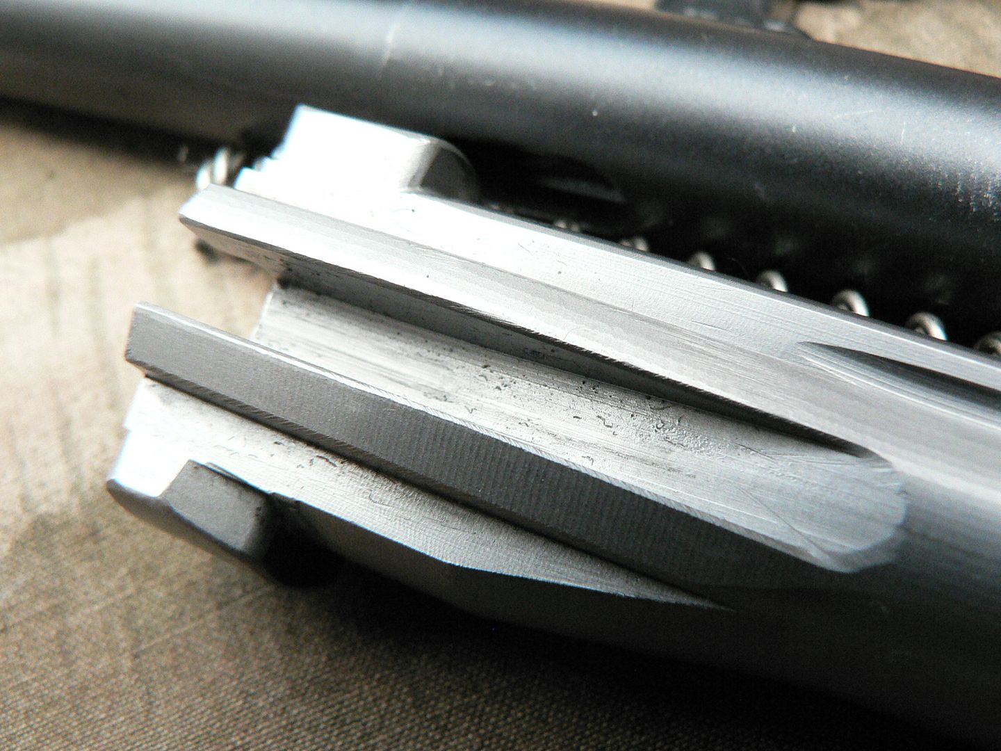 Here are a couple photos of the cam slot showing what is again NORMAL wear:  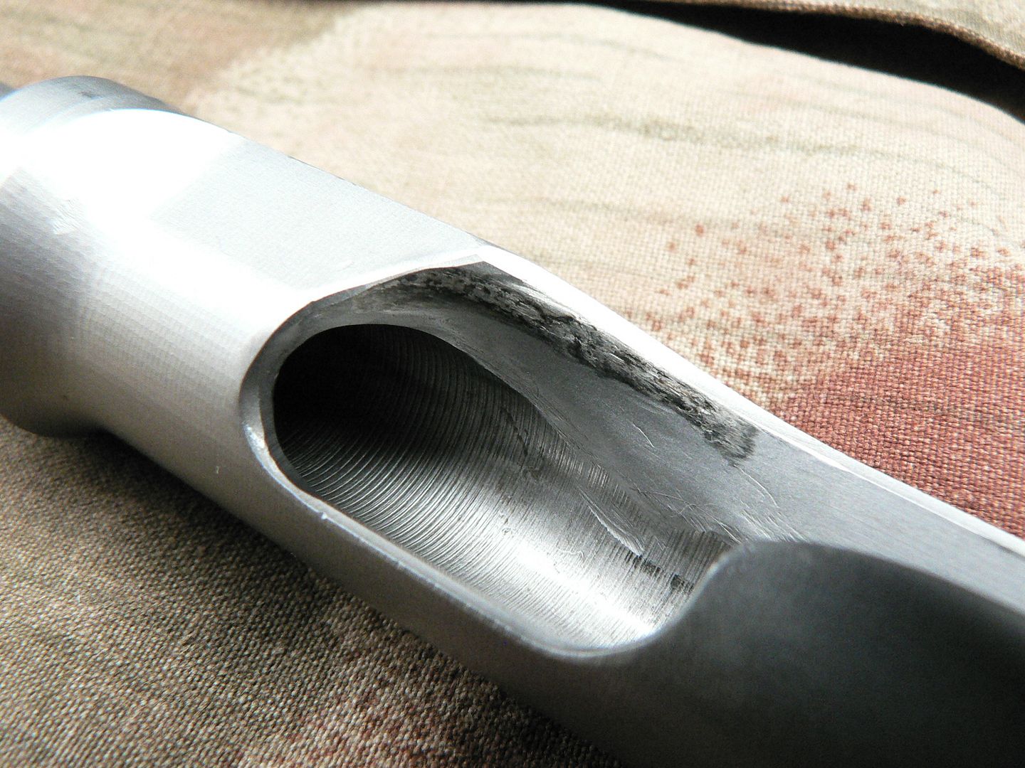 SMG says in the video included with each rifle that you may even start to see chips of metal missing in this area over time. Apparently, it is normal so don't wig out when this starts to happen. Just keep shooting. SMG has over 15,000 rounds through their test rifle so I'll just take their word for it. I know I'll probably never put 15K through mine unless one of you want's to donate some ammo. I don't know what the black marks are in the wear area. It doesn't rub off so I just ignore it. Let's take the extractor apart. Here it is assembled: 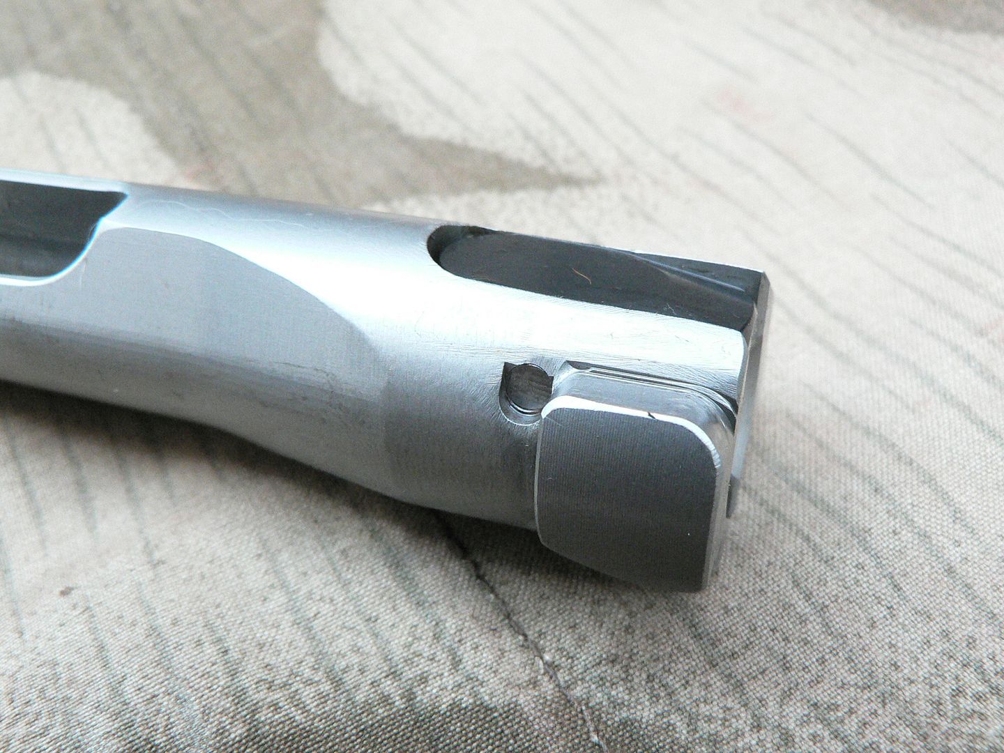 To disassemble, simply press down on the rear of the extractor and use a punch or bullet tip to push the retaining pin out. Here it is shown disassembled: 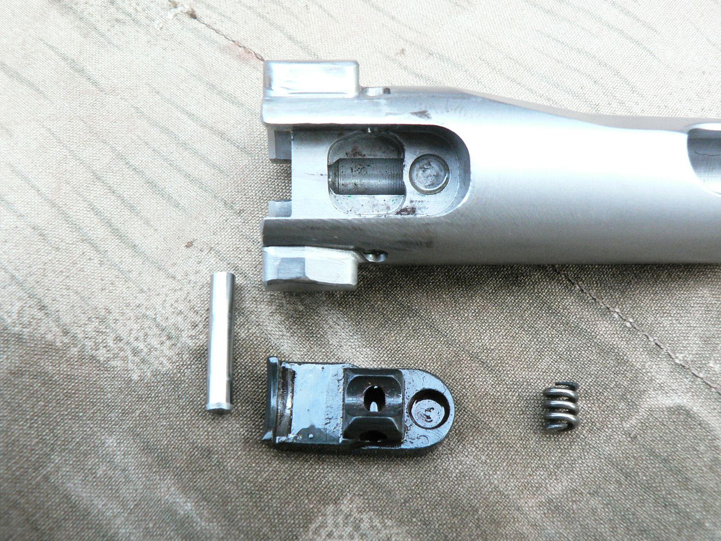 When reassembling the extractor, be careful that the spring engages the cutouts for it in both the bolt and extractor. It's small and can easily be tipped on its side during reassembly. This design is different than an original rifle but I don't know why. I do know that it works just fine. It also comes apart and goes back together very easily which is a big plus after messing with that cursed firing spring plunger earlier. Did mention that part needed to be redesigned? That's it for the bolt. In the next post, we'll start with the bolt carrier and go from there. See you then!
__________________
I promise to be nice and play well with others |
|
|
|
|
10-07-2014, 06:11 PM
|
#15 |
|
User
Join Date: Oct 2007
Location: Maryland
Posts: 340
Thanks: 43
Thanked 107 Times in 51 Posts
|
In this post, we will finish up looking at the rifle itself. To do that, we need to talk about the bolt carrier.
The bolt carrier consists of three basic parts pinned together to make one unit which cannot be disassembled. At the rear is the bolt carrier proper. It holds the firing pin in place via the yolk machined out of it. This yoke also acts as a cam that causes the bolt to rotate as it moves back under gas pressure and forward under spring pressure, unlocking and locking the action in the process. In the middle is the operating rod. Its job is simply to connect the gas piston to the bolt carrier. The charging handle plugs into the operating rod too. Up front is the stainless steel gas piston. It's the part that takes the impact of the gas tapped from the barrel which drives the entire assembly to the rear. We'll start with the rear of the unit: 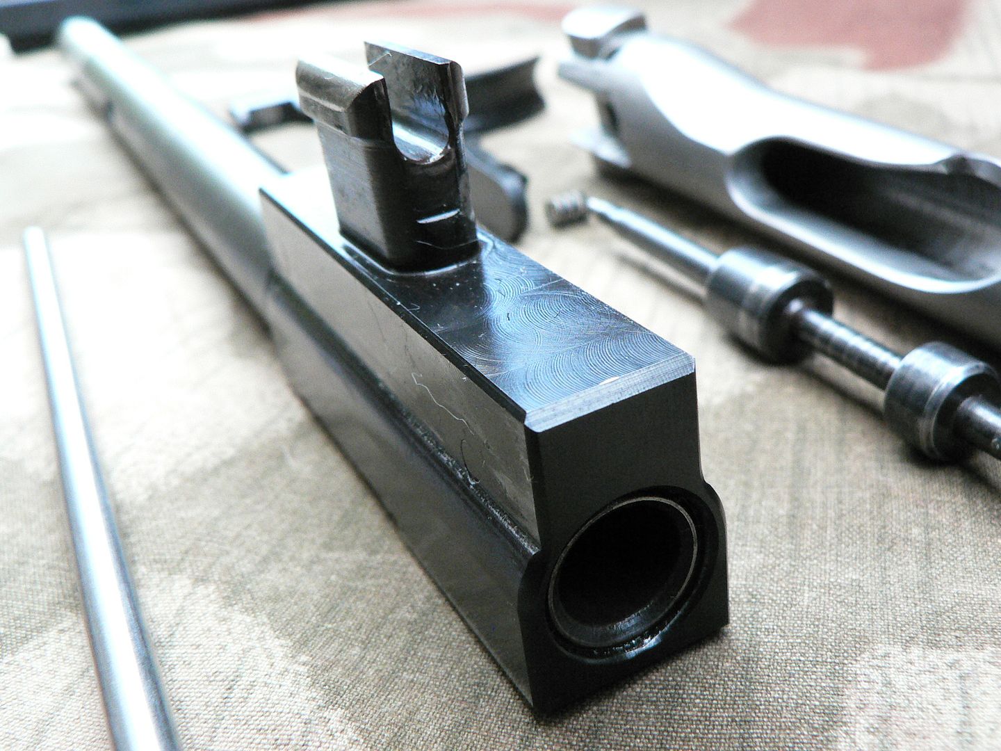 The hole in the rear is where the recoil spring fits. The thing in that hole that looks like an insert is actually the rear of the operating rod. Inserted from the front, it passes all the way through the bolt carrier and is pinned in place. The pin is just barely visible above the step running up the side of the carrier. In this view of the right rear, the pin is more visible: 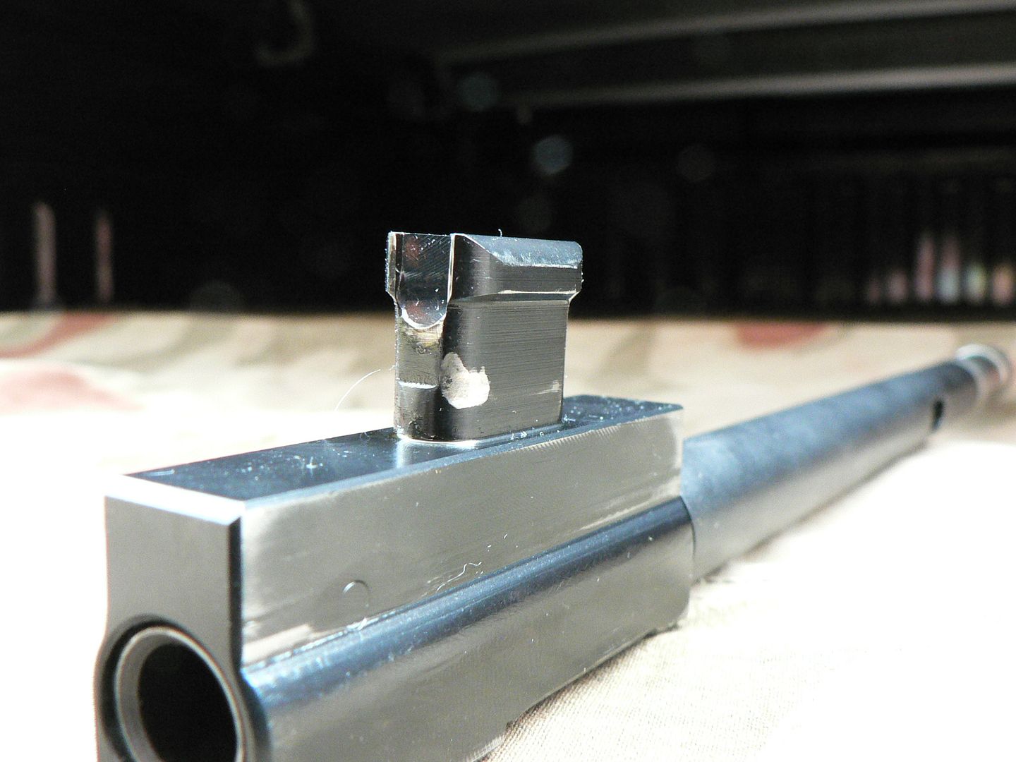 Also of note in the above picture is the wear mark on the right rear corner of the yoke where it contacts the cam slot in the bolt. Here is a view of the front of the carrier showing marks where the left front of the yoke contacts the bolt during operation: 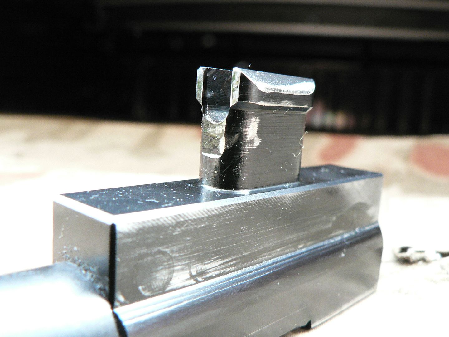 Judging by the circular mark above the step in the side of the carrier, there may be a second pin holding the operating rod place but I'm not sure about that. That mark may simply be a machine mark. I assume that the yoke must take a tremendous beating as it does its job because it was a common failure point in rifles tested during the war. The only thing of interest on the operating rod is the cutout for the charging handle: 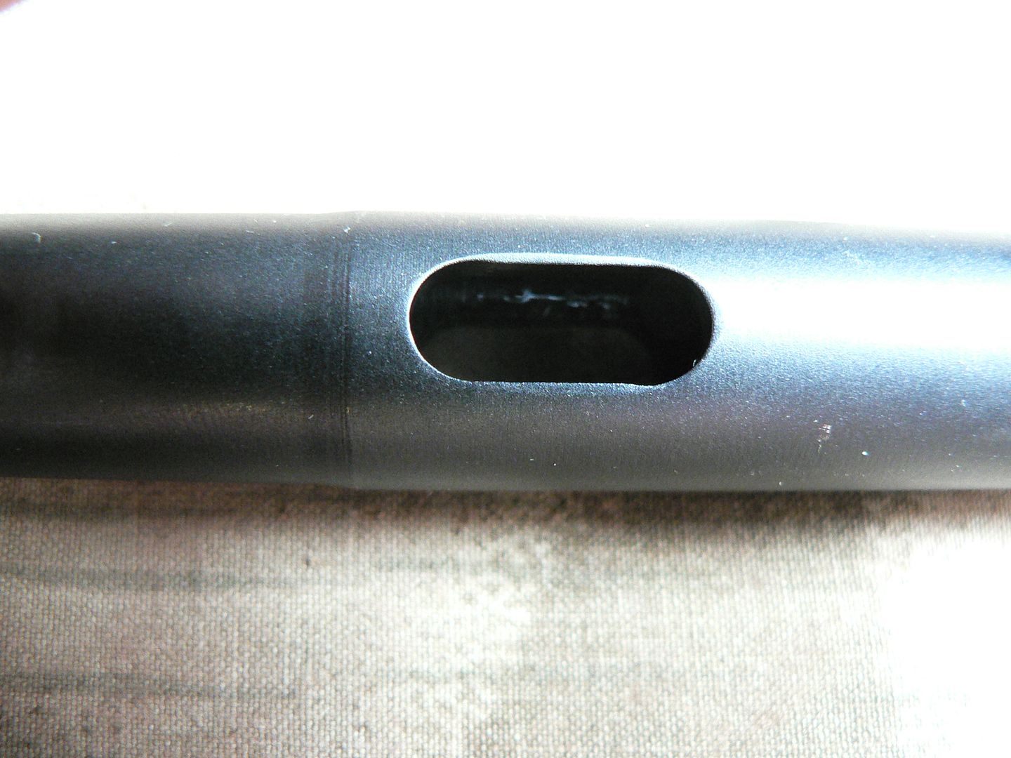 Hidden inside the operating rod is a non removable plunger. When the recoil spring is in place, it pushes the plunger forward and into engagement with a notch cut into the charging handle stem, locking it in place on the operating rod. Here, the plunger has been moved forward until it is visible in the cutout: 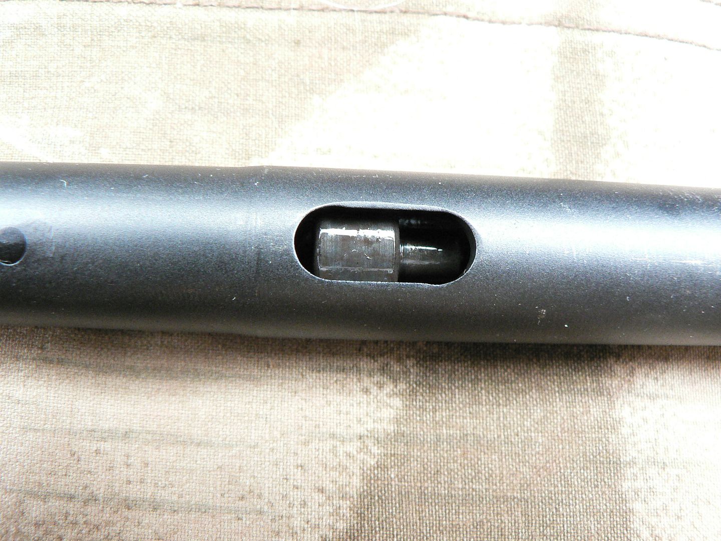 All the way at the front of the assembly is the gas piston: 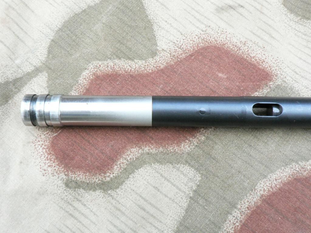 It is inserted into the operating rod and pinned in place. The pin is visible in front of the charging handle cutout. A detail shot of the gas piston: 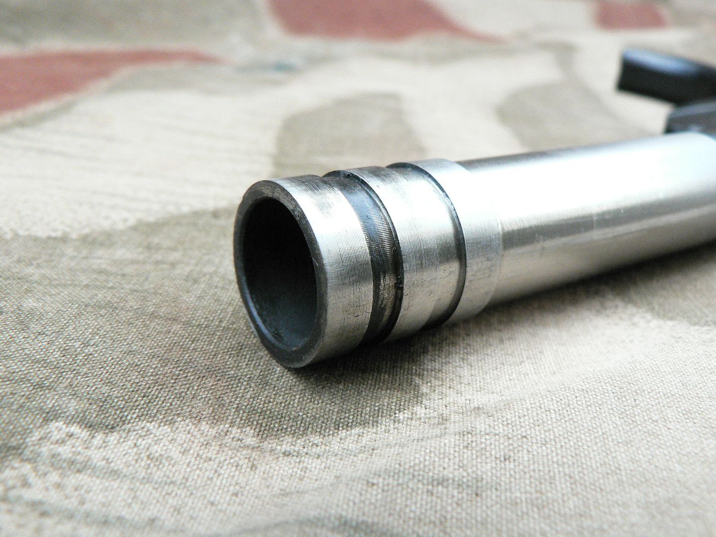 That's it for the internals. Here's a nice neat picture of all the bits and pieces disassembled including the standard round that the rifle fires: 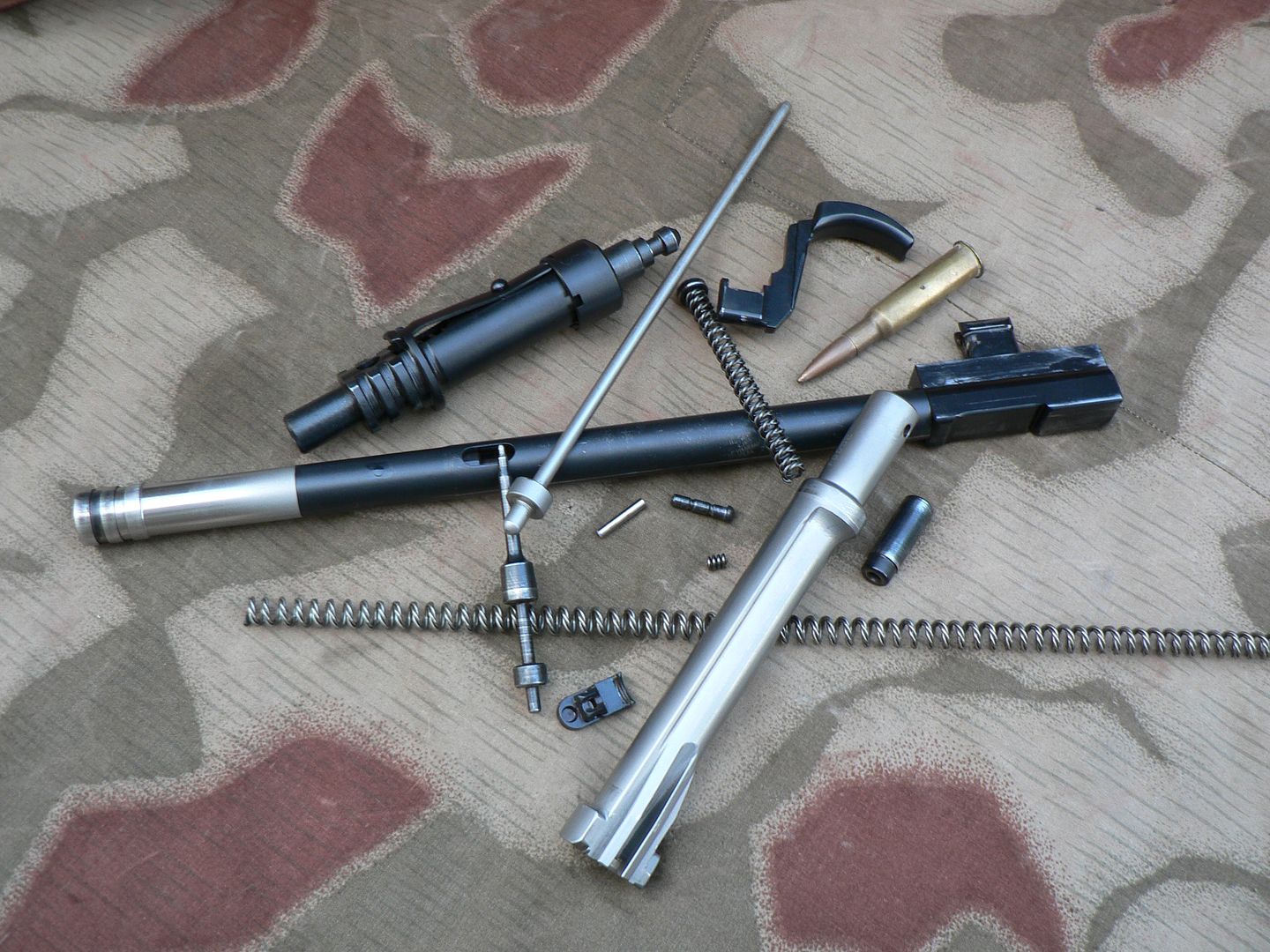 OOPS! How did that 7.62x54 round get in there?? Let's try that again with the proper Turkish 8mm round: 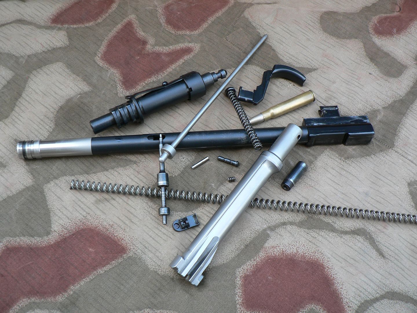 NO NO NO!!! DO NOT UNDER ANY CIRCUMSTANCES SHOOT TURKISH 8mm THROUGH THIS RIFLE. For that matter, don't shoot the Turkish stuff through ANY 8mm rifle except for a bolt action. If you do, you are risking not only your rifle but your life as well. DON'T DO IT!!!! Am I clear on that? Alright, here is a family picture showing all of the internals. I'm not going to list each part because you should already know what they are if you've stayed awake and read everything: 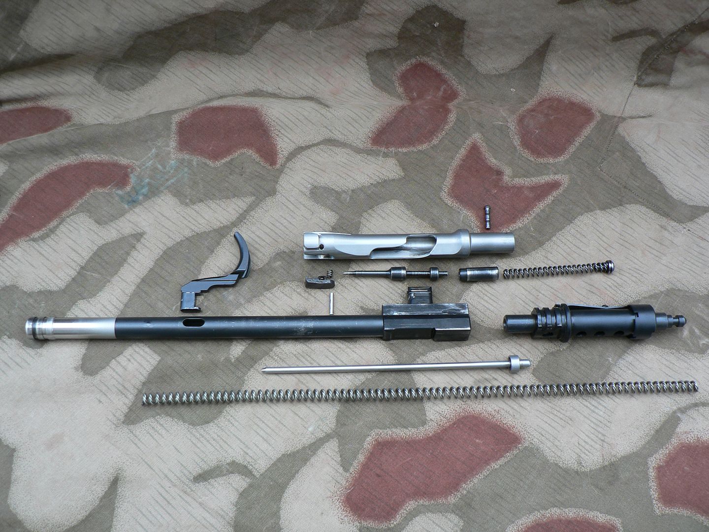 These next photographs are just miscellaneous shots of the empty receiver and a few notes about them. Inside of the magazine well showing how clean the weld line is where it meets the receiver. The only evidence of the weld is a slight hump: 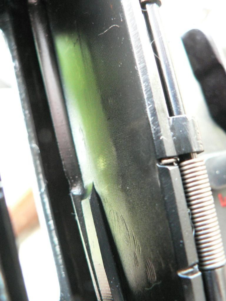 The area at the front of the magazine well which engages the front mounting lug on the magazine: 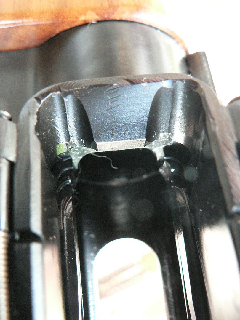 A view through the ejection port showing the single spring used for both the magazine catch and the ejector: 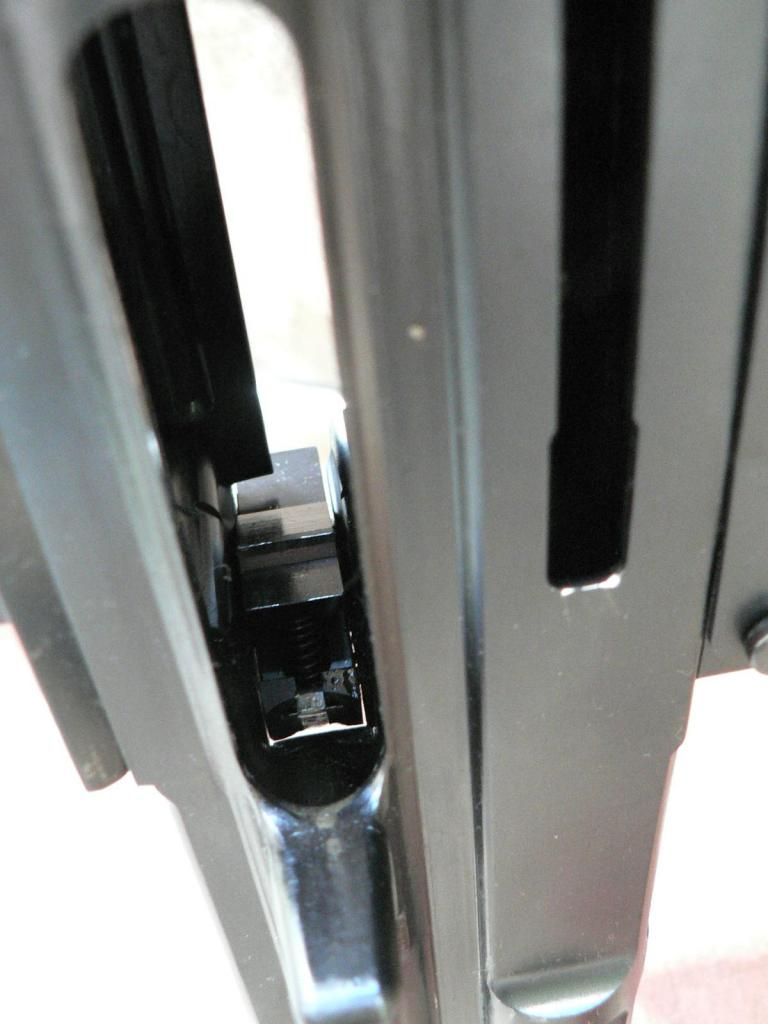 A view up into the breach showing part of the trunnion and one of the cuts for a locking lug on the bolt: 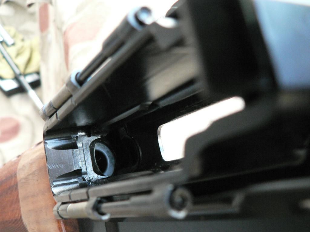 And finally, the ejection port: 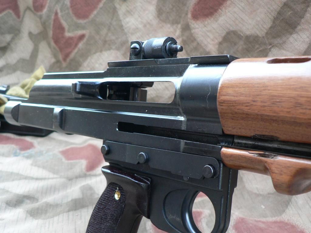 A note about this opening. If you are like me, you'll stick your finger through any opening in the receiver while cleaning in an effort to get to any powder residue and funk that has accumulated through use. DON'T stick your finger in this hole. On my rifle at least, the inside edge of the ejection port was not polished so it's as sharp as a knife. I stuck my finger in there and it was cut on both sides immediately. That felt really nice with Hoppes #9 all over the place........ That's it for the rifle proper. We're in the home stretch. In the next post, we'll start looking at the accessories beginning with the magazine. Bye for now!
__________________
I promise to be nice and play well with others |
|
|
|
|
10-16-2014, 12:01 PM
|
#16 |
|
User
Join Date: Oct 2007
Location: Maryland
Posts: 340
Thanks: 43
Thanked 107 Times in 51 Posts
|
Today, we'll look at the 20 round magazine. This item is the #1 weak point of the rifle because it is not produced by SMG. It is actually a Czechoslovakian made ZB26/30 produced very long ago, as in pre-WWII. The magazines are extremely well made and durable but there are two problems. First, because they have not been produced in 70+ years, there are only so many around. Second, like all magazines of that era, there are inherent variations in the dimensions so that a given magazine may or may not fit your rifle. Back then, the factory tested magazines with each rifle until they found a given number that worked well with that particular rifle. These magazines were then numbered to and issued with it. SMG does the same thing and includes two magazines numbered to the rifle. So far, I have tested five magazines with my rifle. The two that were numbered to it worked just fine as did one of the unnumbered ones. However, the other two unnumbered did not work. One of them had a follower that stuck in the magazine body when loaded past just a few rounds (there are no dents in the body either so I'm not sure what the issue is yet) and the other would not properly lock into the magazine well so it would fall out after just a few rounds. These magazines are not cheap either so it quickly becomes an expensive gamble to buy them untested. But we are not taking this thing to war either so do you really NEED more than two magazines when they are so well made that you will never wear even one of them out? Alright, lets take a look at one.
Here's a 3/4 front view of the ZB26/30 magazine: 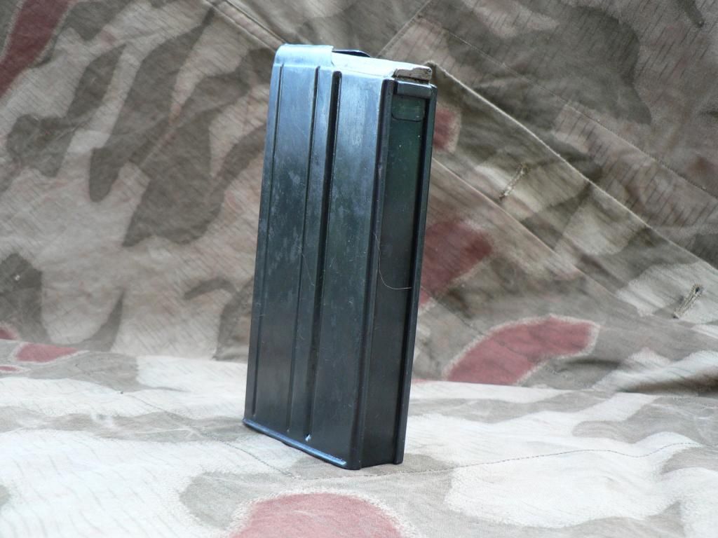 Given its age, there are some blemishes in the blued finish so it doesn't exactly match the new finish on the rifle. No biggie.....just make your rifle match through some hard use! Here's the rear: 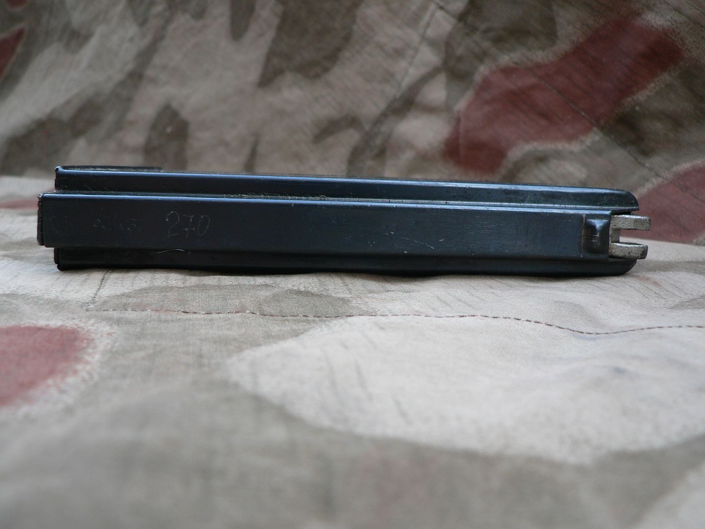 The bit left in the white at the right of the picture is the follower. Some are blued and some are not. When the magazine is empty, the bolt will catch on the follower and hold the action open, just like an original rifle. When you remove the magazine, the bolt will fly home if you do not have a firm grip on the charging handle. DO NOT let it fly home on an empty chamber as this is detrimental to both the chamber face and the sear. Instead, ease the bolt forward after magazine removal. Here's a closeup of the original markings on the rear spine showing that it was made in 1937 and matched to a rifle with a serial number ending in 270: 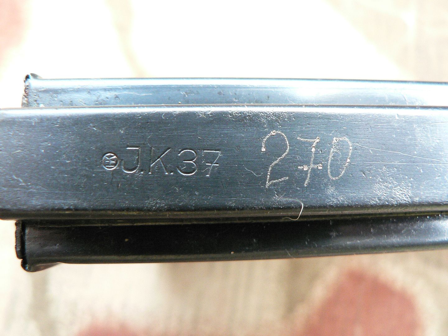 The bottom showing the floor plate with the rear to the right: 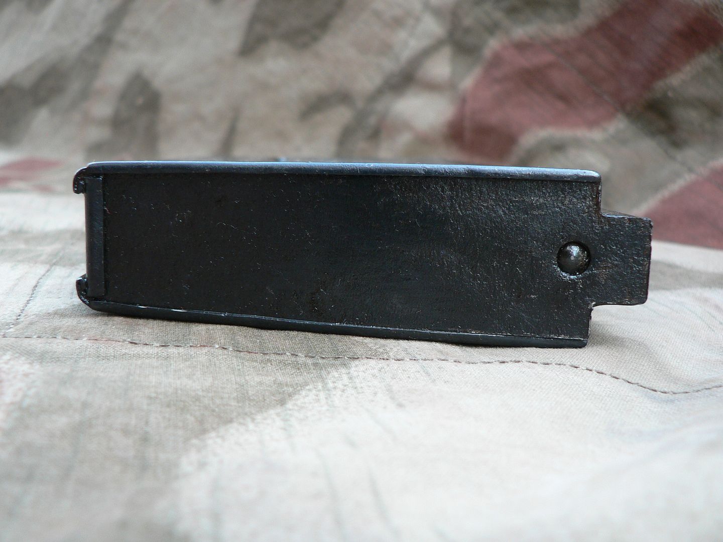 To remove the floor plate for internal cleaning or inspection, use a bullet tip to depress the spring button and slide the floor plate to the rear. So, why use this magazine if it's so old and potentially finicky? Here's whet SMG has to say on the subject: " This was done in an attempt to use a high quality mag that was moderately priced, available, was the right caliber and looked right..." It is a decent visual match to an original magazine as can be seen in this picture with an original on the right: 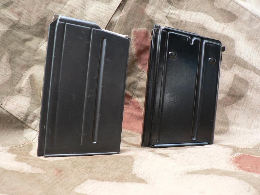 Yes, that is an original WWII German FG42 magazine and NOT a Shoei copy. Original magazines WILL NOT fit into the SMG rifle.
__________________
I promise to be nice and play well with others |
|
|
|
|
10-21-2014, 01:15 AM
|
#17 |
|
User
Join Date: Oct 2007
Location: Maryland
Posts: 340
Thanks: 43
Thanked 107 Times in 51 Posts
|
In this post, we'll be looking at the sling. SMG DID NOT make the sling and I have no idea who did but it was included with the rifle and is supposed to be a reproduction of an original sling. We'll put that to the test by comparing it to an original sling.
Here is a general comparison shot of the two with the reproduction on the right and an original on the left: 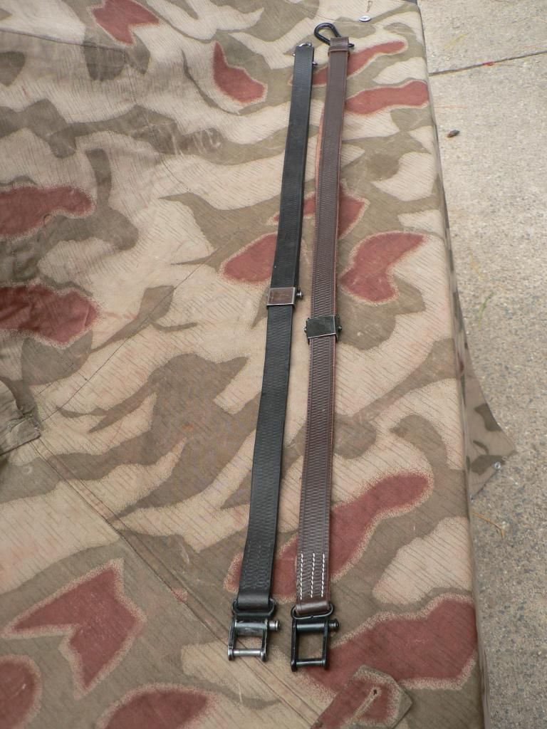 From this distance the repro looks pretty good. Compared to old wartime pictures in a book, it looks really good. On the repro, all hardware is painted black. On the original example shown here, the front carabiner is in the white, the adjustment buckle now has a brown patina but I think it was originally blued and the rear attaching clevis is painted black. I'm sure that there must have been variations on a theme though as is typical of German equipment of that era. Lets move in a little closer and start the comparison in earnest with the front attachment carabiner: 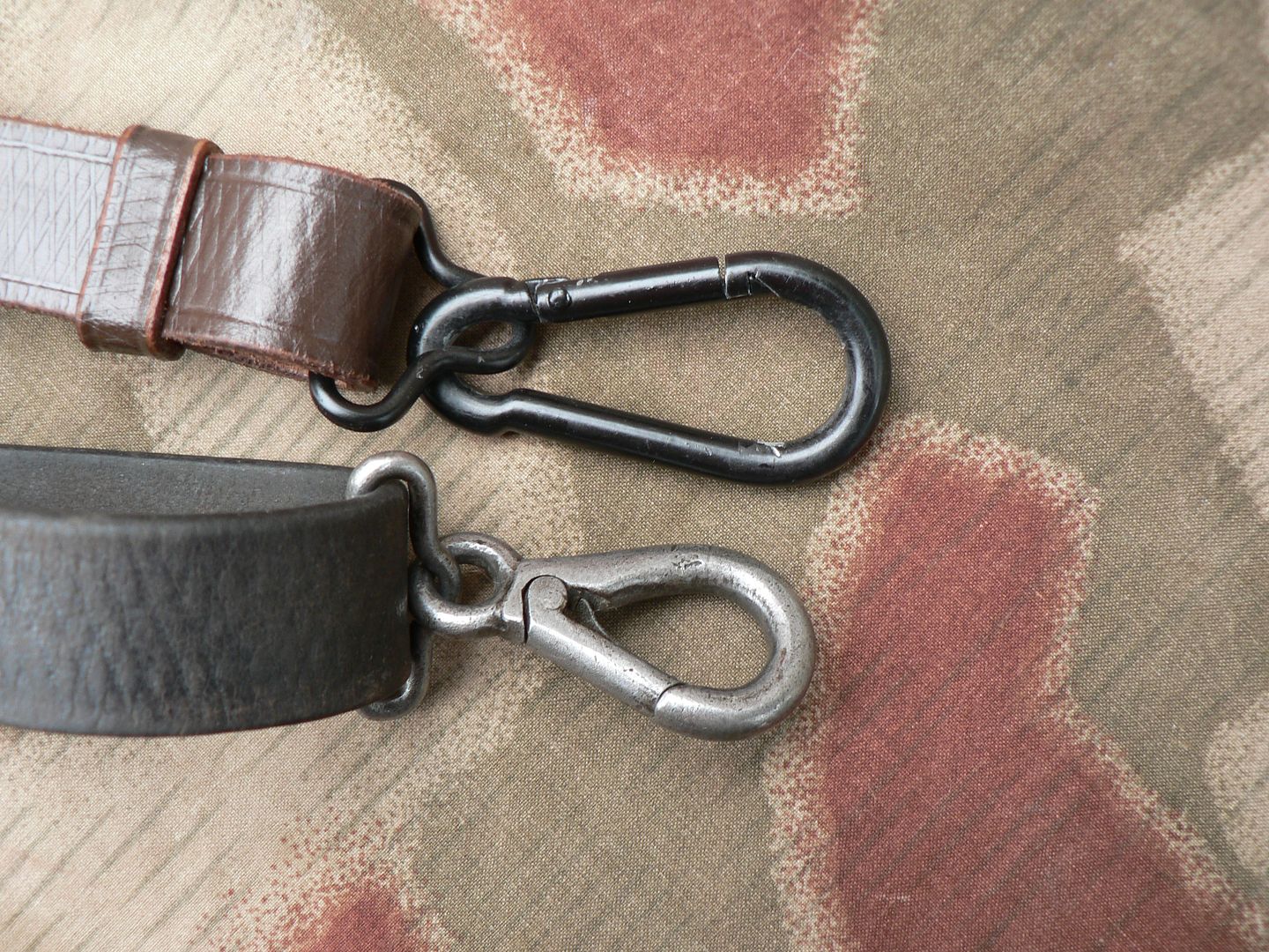 The original is on the bottom in the above picture. The carabiner is made of steel and it's quite heavy. The spring is very stout too. The repro feels cheap and light like it's pot metal or aluminum and the spring is nowhere near as strong. In form, the repro looks absolutely nothing like the original. To be fair though, it seems to work just fine for it's intended purpose but I guarantee you that it would snap easily if you were to abuse it in the field. The original is built like a Panther tank. The diamond pattern on the leather is pretty good and the quality of the leather itself seems to be as good any wartime sling I have encountered. Here's a bottom view of the adjustment buckles with the repro on top: 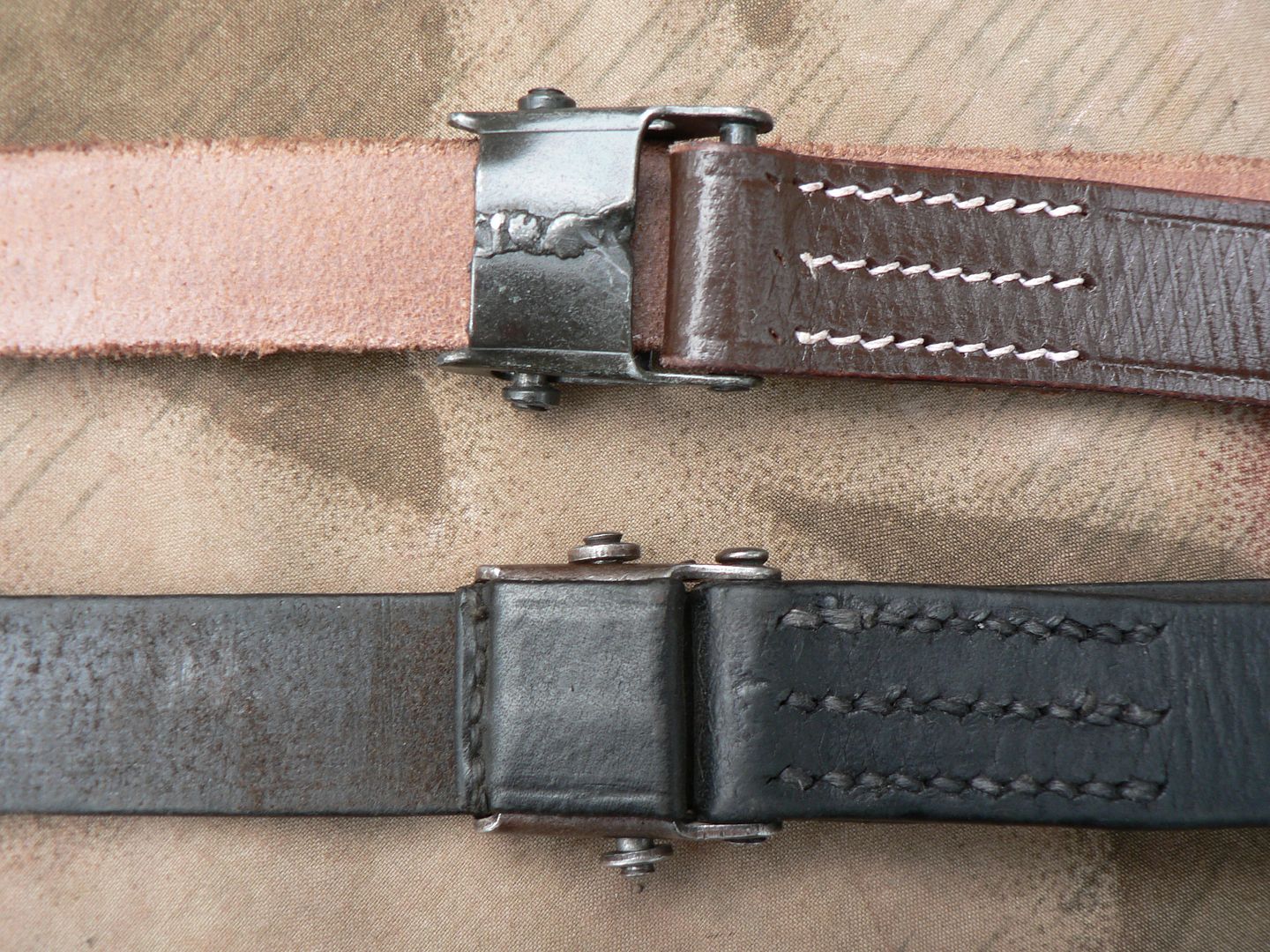 The stitching is as good as the original but the buckle is a joke. The weld is rough, the steel feels like tin and there is no leather wrapped around the bottom. In fact, the entire bottom of the buckle is so misshapen and the lock bar so useless that the buckle does nothing. If you use the sling to lift the rifle, it simply slips in the buckle until it's at maximum length. If you walk with the rifle shouldered, the sling again slips through the buckle until it's at maximum length and the rifle is dangling all over the place. Fail. A side view of the buckles: 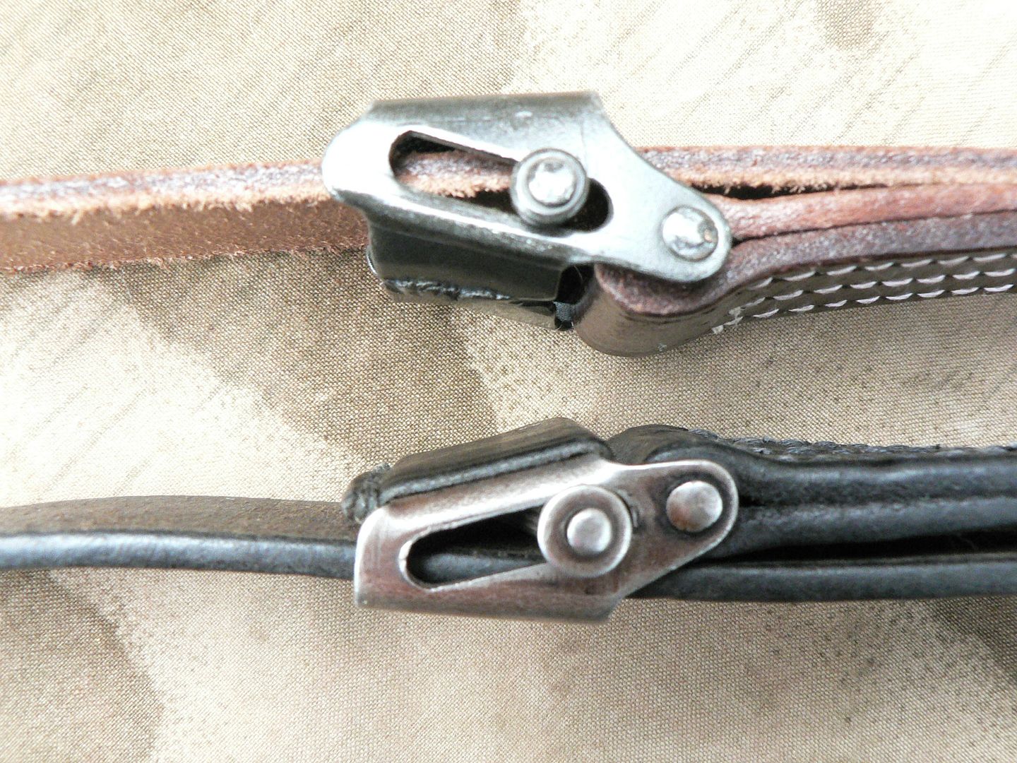 Again, notice how misshapen the bottom of the buckle is. The lock bar is not of a large enough diameter to firmly squeeze the leather between itself and the top of the buckle. The lack of a leather wrap to grab the lock bar just exacerbates the slippage problem. It's just plain worthless. I may try to beat the buckle into something resembling flat and square or I may just use it as a target.....I haven't decided just yet. I really have no use for a product that is cheaply made and doesn't do what it's supposed to do. A top view of the rear attachment clevis with the repro on top: 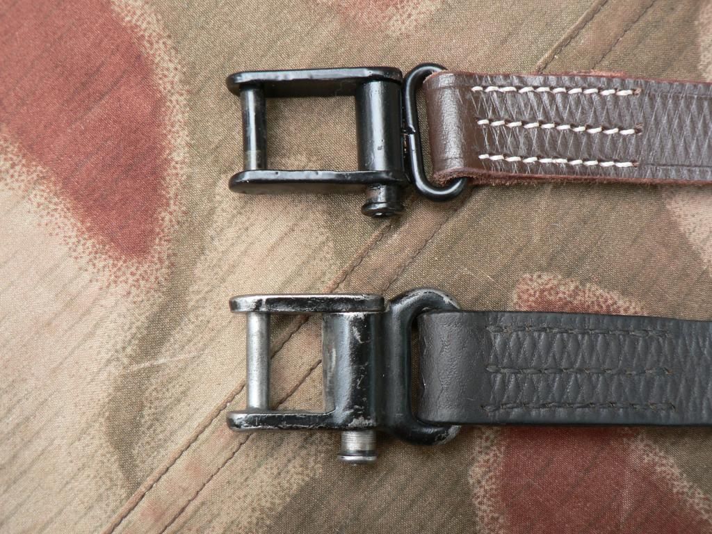 This part kinda' sorta' looks like the original but it's still pretty bad. Notice how the original has the sling loop molded into it while the repro has a poorly shaped and thin oval barely welded to the clevis. Just as with the front carabiner, there is a noticeable weight difference between the two. The lug sticking out the side of the clevis is the push button used to open the assembly for installation on or removal from the stock. Again, the stitching and leather tooling is on the repro is excellent. The pushbutton side of the clevis with the original on top: 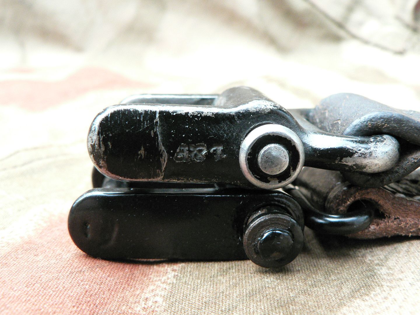 To the left of the picture we can see on the original where the weld holding the pin to the arm was ground down somewhat crudely. We can also see the manufacture mark upside down. L&F was a major manufacturer of slings. On the repro, we can see the weld for the pin through the paint. While the spring on the repro seems to be as strong as on the original, the push button does not operate anywhere near as smooth. This last shot is the other side of the clevis with the repro on top: 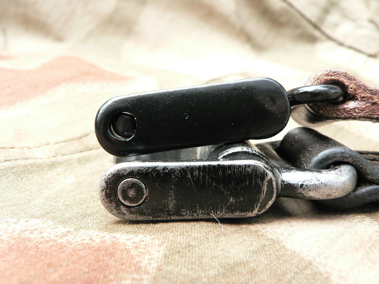 Notice on the repro that the pin is not flush with the surface of the arm. That's because neither the pin nor the hole in the arm is perfectly round so the pin will not fully seat. Big thumbs up on that. It works but it won't hold up to real use. On the original, the pin properly seats in the arm. We can also see grind marks to the weld holding the arm to the pushbutton. By now, I'm sure you have guessed that I do not hold the repro sling in high regard. The leather, leather tooling and stitching are all first class but the whole thing is ruined by the cheap to the point of worthless hardware. I guess it's good that someone is at least trying to make one and it's fine for display I guess but it's junkola if you plan to actually use it. As for calling it a "reproduction", you might get away with that word if you've only seen an original in old photographs or at a distance but when sitting next to an original, I think the words "cheap knockoff" are a more fitting description. Being that there were various sling manufacturers during the war, maybe one of them actually made one that looked like the "reproduction" pictured here but since originals are not to be found in abundance, this example is the best I could come up with for comparison purposes. Whatever the case, I can't recommend this sling unless someone upgrades the hardware. In the next post, we'll look at the scope and mounting rings. I am much more enthusiastic about those because they are as good as originals (probably even better in the case of the scope) and a worthwhile addition to the SMG FG42 if you ask me.
__________________
I promise to be nice and play well with others |
|
|
|
|
10-21-2014, 05:04 AM
|
#18 |
|
User

Join Date: Mar 2008
Location: Marco Island, Florida
Posts: 4,867
Thanks: 1,685
Thanked 1,916 Times in 1,192 Posts
|
As a small side note. The FG series of rifle sling is similar if not identical to the one used on the MG34-42 series of weapons. Originals are still available at reasonable prices.
|
|
|
|
|
10-21-2014, 09:42 AM
|
#19 |
|
User
Join Date: Oct 2007
Location: Maryland
Posts: 340
Thanks: 43
Thanked 107 Times in 51 Posts
|
Doh!! I can't believe that I didn't think of that.....they are not identical but you are right about them being similar.....thank you! That's what I need to do is get one of those slings. A great idea and I thank you very much!!
__________________
I promise to be nice and play well with others |
|
|
|
| The following 2 members says Thank You to Wilhelm for your post: |
|
10-21-2014, 12:12 PM
|
#20 |
|
User
Join Date: Mar 2008
Location: Marco Island, Florida
Posts: 4,867
Thanks: 1,685
Thanked 1,916 Times in 1,192 Posts
|
Happy to oblige! An excellent review of the FG semi with stunning photos, BTW.
I really appreciate the time and effort you have put into this series! |
|
|
|
| The following 2 members says Thank You to alanint for your post: |
 |
|
|


 Linear Mode

