When I have more than one project waiting for space & tooling on the mill table, I try to plan to do similar machine operations together. So if I'm using the rotary indexing head ['superspacer'] to mill the Luger front sight, I'll follow that with another comparable procedure.

Following the Luger front sight, while I had the 80+ pound superspacer on the table, I set up a jig to mill curved slots in 1911 triggers. The JT Masen Co used to offer a skeletonized long trigger for the 1911. It was similar to the Colt Gold Cup trigger, but with the narrower trigger blade in the 1911. (The Gold Cup blade is .350" wide; the 1911 is .250"). They no longer offer it, and other vendors offer other styles of skeletonized triggers but not with the Gold Cup profile.
But JT Masen does still sell the steel long 1911 trigger, so I decided to make my own skeletonized triggers.

But I needed to design a jig to hold the trigger, and revolve it while milling the curved slot. It took me a week of 3-4 hour workdays to turn out a satisfactory piece. Two of those days were trial & error with wood mockups, trying to figure out how to locate the piece in the jig and then rotate it.
")
Here's the finished jig, with a 'raw' trigger in place. Looks simple, and it is, but it was a PITA to design.

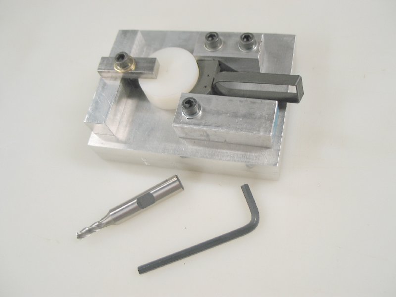
It's only about 3 inches by 4 inches, aluminum, and clamps in a 4-jaw chuck mounted on the rotary indexing head. Here's how it works...
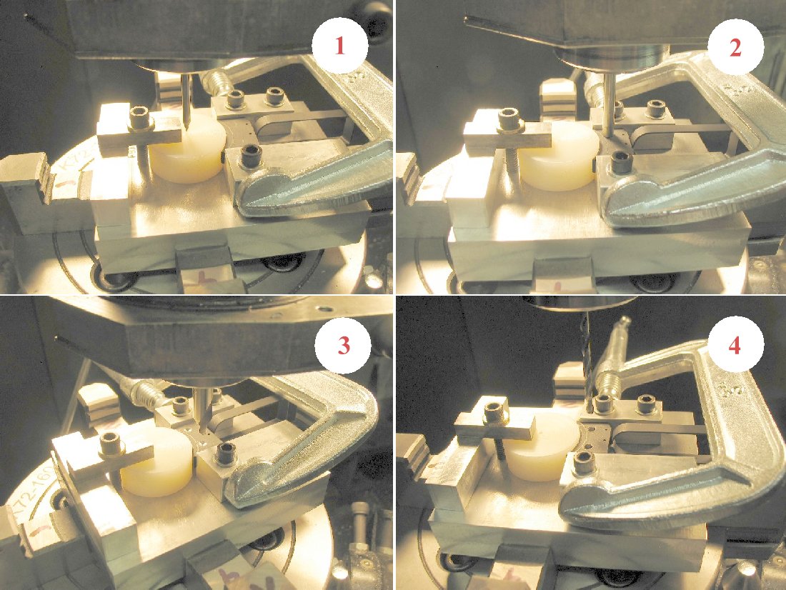
1. The 'raw' steel trigger is clamped in the jig, resting against a Nylon disk with a dimple in the exact center. A steel pointer is chucked in the mill quill and centered on the dimple.
2. I want my slot to be 3/32" away from all three edges of the front of the trigger, so I chuck a 3/16" drill rod in the quill chuck and locate it 3/32" from the edges.
3. Now I center drill each end, just a shallow indentation.
4. I drill through each end with a 1/8" drill.
Moving to next pic...
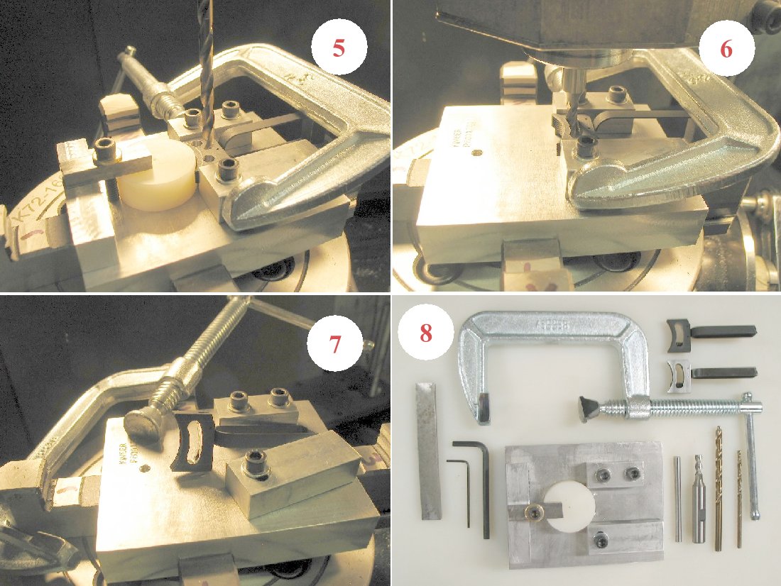
5. Next I enlarge the two holes to 3/16".
6. Finally I load the 3/16" 4-flute end mill and start rotating the indexing head along the curve. The centerline of the curve is ~.875" from the center dimple of the Nylon disk. I take .020" cuts, and rotate slowly, to eliminate or at least reduce the tendency of the thin end mill to 'wander'.
7. Completed slot.

8. The tooling used. The C-clamp has been ground to allow low mounting. The C-clamp actually secures the trigger between the two aluminum blocks; the socket head cap screw just holds the trigger flat against the base.
My next project will be to make up a 'plug' to allow quick centering of the indexing head under the quill. I've been just marking the table with a magic marker but the marks keep rubbing off. A plug in the center of the indexing head that can be centered under the quill with be a real time saver.
