You are most welcome!
The trigger housing is off. Let's take a look a closer look at it.
Here's a view from above looking down into it forward is to the right:
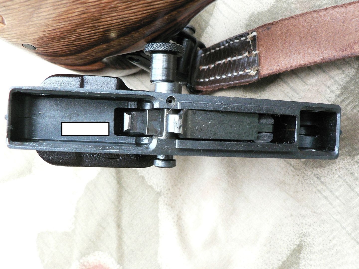
Let's start at the front and work our way back. The first thing we come to is a hollowed out square area. This fits over the front retaining lug hanging from the bottom of the receiver. The front retaining pin passes through the retaining lug. Moving rearward, we come to the fire control group (FCG). All the way to the front of the FCG is the top of the trigger. It has a slot cut into it where the disconnector/sear trip connects to it using a pin. The disconnector/sear trip is one part and it has two lugs sticking up. One is about midway back with the safety axle passing below it and the other is all the way at the rear of the FCG. The lug above the safety axle is the disconnector trip. It is pushed downward as the bolt carrier passes over it, disconnecting the sear trip from the sear and producing semi automatic fire. The rear lug is the sear trip and it pulls forward on the bottom of the sear (mounted in the receiver) as the trigger is pulled. This rotates the sear on its pin and out of contact with a notch in the bottom of the bolt carrier. The bolt carrier then slides forward creating good times and good memories at the range! Behind the FGC is a white rectangle. This white rectangle is where the serial number is etched into the frame but I covered it up. I hated to do that but in todays political climate, and due to the dictatorial state I live in, I feel it necessary unfortunately. All the way at the rear is where the rear retaining lug goes to be captured by the rear retaining pin. The safety is shown in the "F" (Fire) position. To place it in the "S" (Safe) position, the knurled knob is pulled slightly outward and rotated to the rear. This disconnects the FCG from the sear.
IMPORTANT: The safety is to be rotated to the "S" position ONLY when the rifle is cocked or the housing is removed from the receiver! It MUST be in the "F" position before the charging handle is pulled to the rear or when the housing is being reattached to the receiver! Failure to follow this advice WILL cause headaches!!
The left wall of the trigger housing has a small hole with a black dot in it above the trigger axle. This hole is where the safety axle detent and detent spring are inserted during assembly. The black dot is a hole drilled through the safety axle. I assume that it serves as an oil hole for the detent and its spring but I don't know that to be fact. Now, before you deviants go thinking that all you have to do to convert this thing to fully automatic is grind off the disconnector trip, think again. The geometry of the disconnector/sear trip is such that, when the rifle is fully assembled, it will automatically disconnect itself from the pulled trigger anyways. I'm NOT going to go into how all of that works though. If you look very closely at the above photograph, you can see a faint line in the middle of the grip housing where the two halves meet. It is most noticeable rear of the white rectangle and just in front of the trigger. Fantastic fitting is in evidence here.
Let's look at just how well the two halves of the trigger housing are joined:
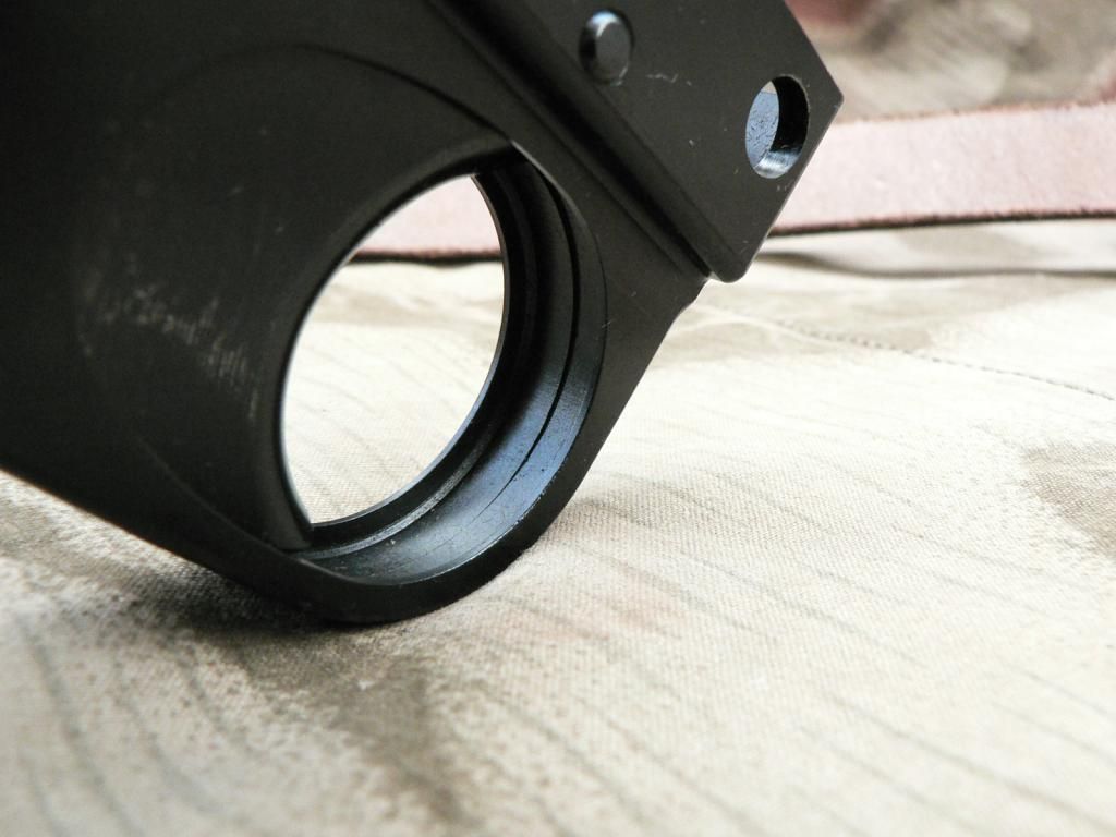
The above picture shows the non-welded side of the seam. Notice that the part of the seam just in front of the bottom of the trigger is flawless. As you go around towards the top of the trigger, the halves do not fit perfectly with one rising above the other creating a ridge. That is NOT a gap but is where the radius of the left half is less than that of the right half. Please do not construe this as a complaint, only an observation. In reality, this area is so small and the ridge so minor that most would never even notice it. It has absolutely no effect on functioning and is cosmetic only.
Here is the welded seam on the outside of the trigger housing:
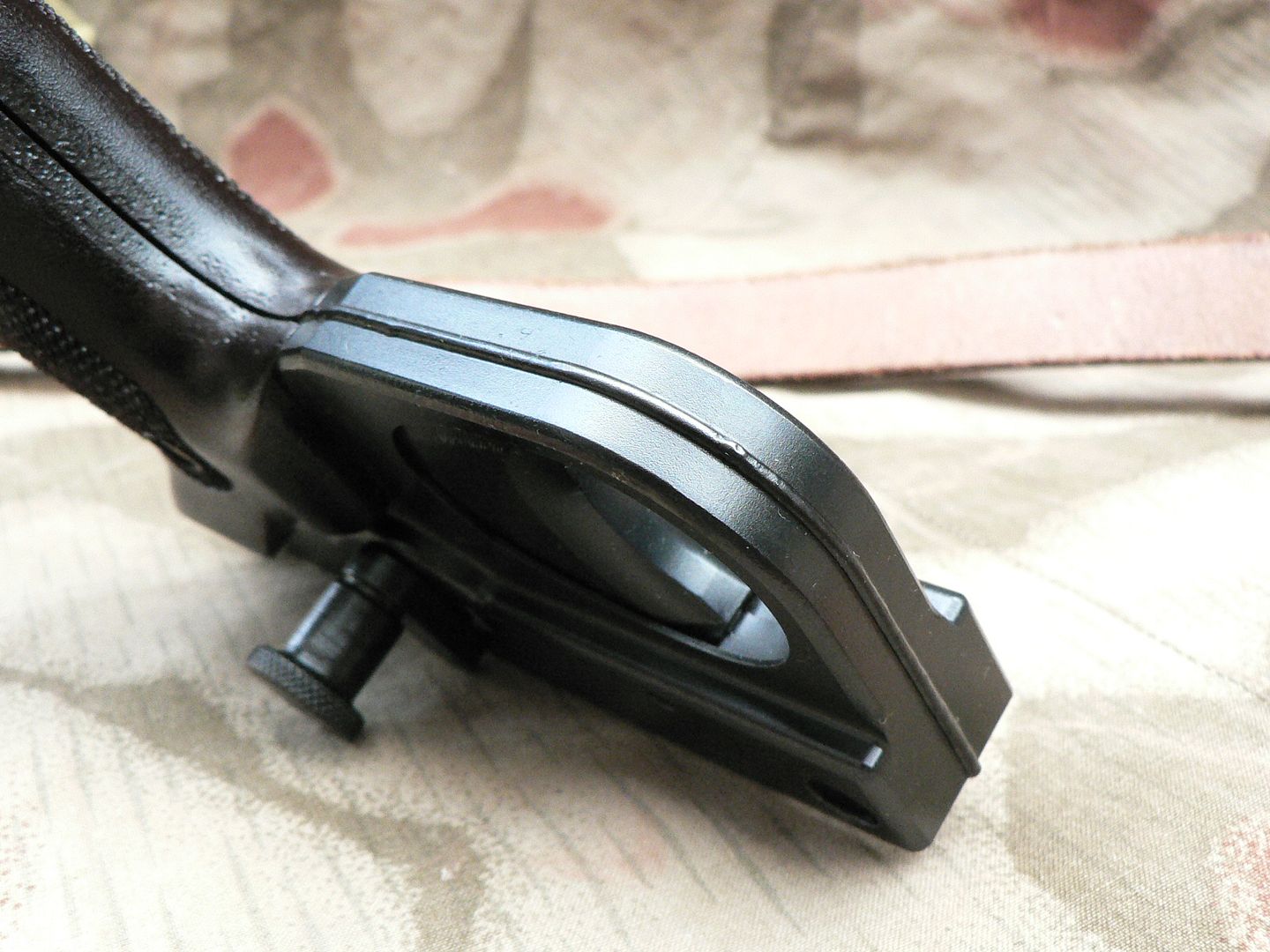
In my opinion, the work is impeccable. If anything, it's TOO good for a reproduction.
Here's the whole thing disassembled:
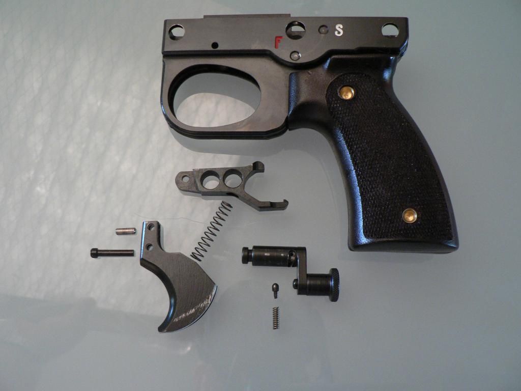
Starting from the top, we have the housing with the disconnector/sear trip below it. This part has three holes in it. The front (left) hole is for the pin that connects it to the trigger. The next two larger holes serve no purpose other than reducing weight (I guess). At the middle top of the part is the disconnector trip. All the way at the rear is the sear trip. Moving down, we have the trigger/disconnector spring. The top of the spring is pointing at the recess in the bottom of the disconnector/sear trip. The spring fits into this recess. The bottom of the spring is pointing to a similar area in the trigger where it fits. In front of the trigger are two pins. The top pin connects the trigger to the disconnector/sear trip. The bottom pin holds the trigger into the trigger housing. To the right of the trigger is the safety. You can clearly see the spring loaded nub that fits into the "F" and "S" recesses on the housing, locking the safety in the desired position. Below the safety is the safety detent and detent spring.
To disassemble the trigger housing assembly:
1. Rotate the safety midway between the "F" and "S" positions.
2. Wiggle the safety as you pull it to the left out of its hole in the trigger housing. The disconnector/sear trip will pop up.
3. Remove the trigger spring, safety detent and detent spring.
4. Remove trigger pin by pushing out of trigger housing from left to right.
5. Remove trigger/disconnector/sear trip assembly. These parts can be taken apart by pushing out their pin in either direction.
Reassembly is the reverse of the above but be forewarned, it CAN be fidgety to get back together.
The entire FCG has been redesigned from what was originally made by the Germans. The original FCG is quite complex with most of that complexity being due to the fact that it was select fire. All of that mess just wasn't necessary with a semi auto only rifle so, this is the result. The less than ideal trigger pull is due to the design of the rifle, NOT the design of the FCG. In a normal system, the only pressure you have on the sear is the relatively weak force of a striker spring or a hammer spring. In this design, we have the force of both a double wound firing pin spring AND a double wound recoil spring to contend with. Both of these springs are trying to push the bolt carrier home but are being stopped by the sear. In other words, there is ALOT of pressure being exerted on the sear. That accounts for the fairly heavy trigger pull. As soon as get a chance to contrast it to the trigger pull in an original (and that IS going to happen) I will report back on that.
One last picture showing the area of the trigger where the trigger spring fits:
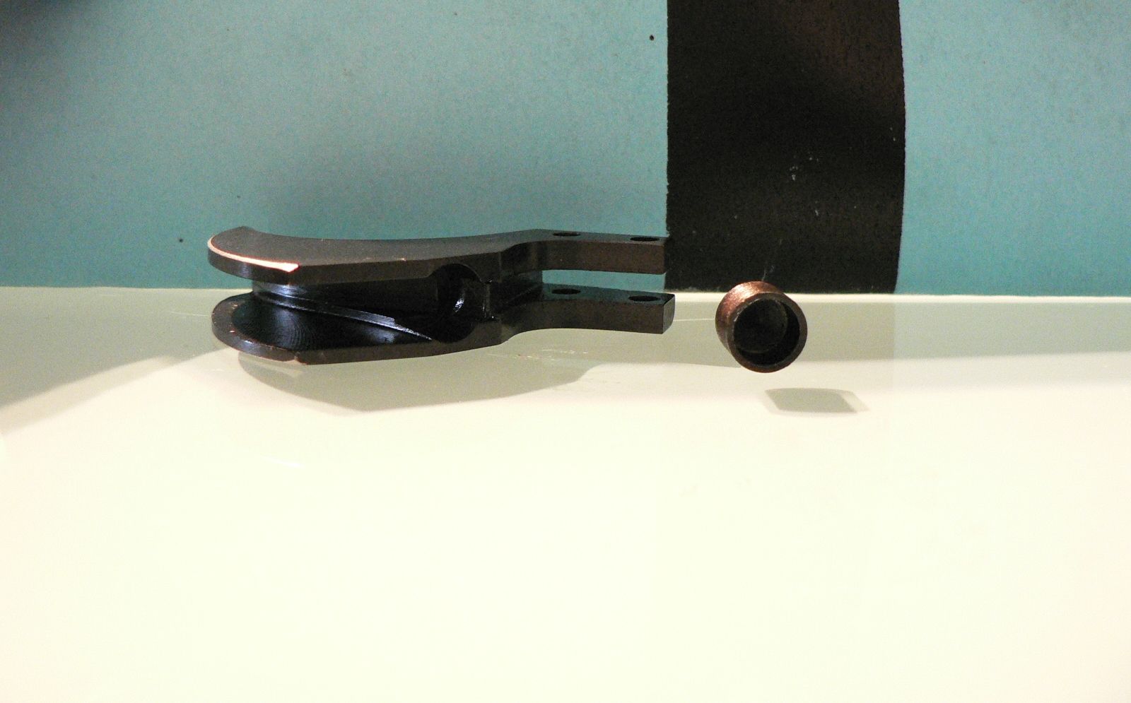
We're looking at the back of the trigger and it's on the left. On the right is a spring cup. This cup fits into the corresponding hole milled out of the back of the trigger. The spring then fits into this cup.
Okiedokie, I think that's it it for the trigger housing assembly.....I think. If I forgot anything, I'll get it in the next post!